# PMW3901-Based Flow Sensors
PMW3901 is an optical flow ASIC that computes the flow internally and provides a difference in pixels between each frame. It uses a tracking sensor that is similar to what you would find in a computer mouse, but adapted to work between 80 mm and infinity. The PMW3901 is used in several products, including some from Bitcraze, Tindie, Hex, Thone, and Alientek
This topic provides links to sensors that have been tested, along with information about mounting and PX4 configuration (this is common to all sensors of this type).
# Boards using PMW3901
The following table shows some of the boards that use this sensor, listing the number of interfaces, the number of sensors, the input voltage, and the size. The board name links to board-specific sections that include wiring and purchase information.
| Manufacture | Board | Interface | Flow | 测距仪 | Gyro | Voltage (V) | Size (mm) | Max Height (m) |
|---|---|---|---|---|---|---|---|---|
| Bitcraze | Flow breakout | SPI | Y | Y | - | 3 - 5 | 21x20 | 1 |
| Tindie | PMW3901 Optical Flow Sensor | SPI | Y | - | - | 3 - 5 | AxB | - |
| Hex | HereFlow PMW3901 Optical Flow Sensor | CAN | Y | Y | Y | 3 - 5 | AxB | 4 |
| Thone | ThoneFlow-3901U | UART | Y | - | - | 3 - 5 | AxB | - |
| Alientek | ATK-PMW3901 | SPI | Y | - | - | 3.3 - 4.2 | 27.5x16.5 | 1 |
# External Rangefinders
An external rangefinder/distance sensor is required for the sensors that don't have a rangefinder (e.g. Tindie or Thone) and recommended for the other boards (as their range is quite limited).
The range needed is dependent on the application:
- Indoor flight: ≈4 metres
- Outdoor flight: ≥10 metres (e.g. to support the position control in environments where GPS might have issues)
Any rangefinder/distance sensor supported by PX4 may be used. The sensor can be mounted anywhere but must point down, and should be connected/configured as usual.
提示
The PX4 team mainly tested using the Lidar Lite V3 on larger vehicles and the Lanbao CM8JL65 on smaller vehicles.
# Mounting/Orientation
Flow modules are typically mounted near the centre of the vehicle. If mounted off-centre you will need to set offsets: Optical Flow > EKF2.
The flow modules may be mounted with any yaw orientation relative to the vehicle body frame, but you must set the value used in SENS_FLOW_ROT.
The "zero" rotation is when the sensor board and vehicle X-axes are aligned (i.e. the "front" of the vehicle and the board are in the same direction), with rotations increasing in a clockwise direction.
PMW3901 modules have a small notch indicating the direction of the back of the board. The diagram shows the relative board and vehicle orientations that correspond to SENS_FLOW_ROT=0 (note the notch at the back).
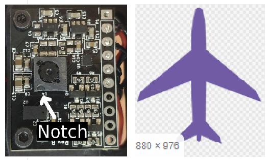
The diagram above shows the Bitcraze board. You can use the notch to find the orientation of the other boards in the same way:
Tindie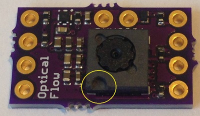 | Hex Hereflow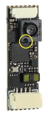 |
Thone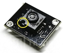 | Alientek (also has an arrow indicating the front!)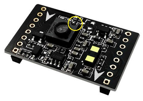 |
# PX4 配置
The PX4 configuration that is common to all PMW3901-based boards:
- Optical Flow > EKF2 explains how to fuse optical flow data in the EKF2 estimator and set position offsets for the mounting position of the flow sensor.
- SENS_FLOW_ROT sets the orientation of the flow sensor relative to vehicle heading.
In addition for:
- SPI-connected sensors you must set SENS_EN_PMW3901 to
1in order to enable the sensor driver. - UART-connected sensors (e.g. ThoneFlow-3901UY) you must configure the associated serial port by setting the parameter SENS_TFLOW_CFG to the value of the connected UART port (for example, if you connected this sensor to
TELEM 2, you need to setSENS_TFLOW_CFGto102). - UAVCAN sensors you must set
UAVCAN_ENABLEappropriately. For more information see UAVCAN Peripherals (and the HereFlow PMW3901 docs below).
Individual flow sensors are further setup/configured as described in the sections below.
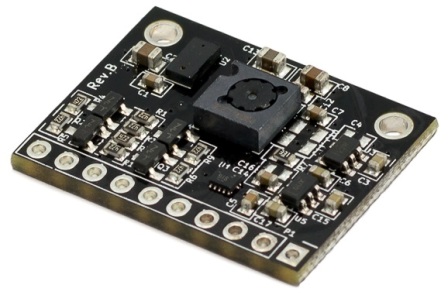
# Bitcraze Flow Breakout
The Bitcraze Flow breakout (opens new window) directly exposes the SPI interface from the PMW3901 module.
The board also incorporates a distance sensor wired to the Pixhawk I2C port. This distance sensor is the VL53L0x ToF sensor from STMicroelectronics. The sensor range is minimal (2 metres) and will be reduced when flying in the sunlight. We therefore highly recommend that you use an external distance sensor.
PX4 configuration and mounting/orientation instructions are provided above.
# SPI Wiring
The PMW3901, if connected to the SPI port on a Pixhawk 4, will automatically detect the Bitcraze flow module. This device's driver was explicitly written to be plugged into the SPI port using the chip select 1. No parameters will have to be configured other than the orientation and position of the sensor.
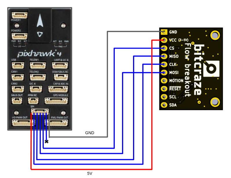
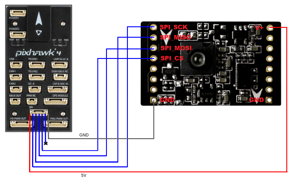
The pinout mapping for the Pixhawk SPI port to Bitcraze Flow Board is shown below (the port mapping is the same for all Pixhawk FMU versions).
| Pixhawk SPI Port (from left to right) | Bitcraze flow board |
|---|---|
| 1 (VCC) | VCC |
| 2 (SCK) | CLK |
| 3 (MISO) | MISO |
| 4 (MOSI) | MOSI |
| 5 (CS1) | Do not connect |
| 6 (CS2) | CS |
| 7 (GND) | GND |
To connect the bitcraze flow board to the Pixhawk, you will need to solder the wires of the Pixhawk SPI cable to the flow board. An SPI cable has 7 wires, from which you need to connect 6 to the flow board.
The following diagram shows how to wire the sensor to a Pixhawk 4.
# I2C Wiring
The I2C wiring is the same for any other distance sensor. Simply connect the SLA, SLC, GND, and VCC to the corresponding (same) pins on the Pixhawk and the sensor.
# Tindie PMW3901 Optical Flow Sensor
The Tindie PMW3901 Optical Flow Sensor (opens new window) exposes the SPI interface from the PMW3901 module exactly as on the Bitcraze module (see SPI Wiring).
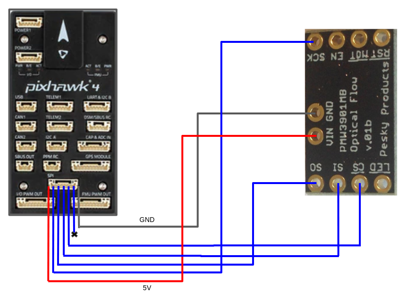
The sensor doesn't have a distance sensor onboard, so you will need to use an external distance sensor.
PX4 configuration and mounting/orientation instructions are provided above.
# AlienTek ATK-PMW3901
The AlienTek ATK-PMW3901 (opens new window) exposes the SPI interface from the PMW3901 module in the same way as the Bitcraze module (see SPI Wiring).
The board also incorporates a distance sensor (we recommend that you use an external distance sensor). You can wire the internal sensor to the Pixhawk I2C port in the same way as any other I2C peripheral. A screenshot showing the I2C pins (SLA, SLC, GND, and VCC) is provided below.
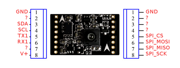
PX4 configuration and mounting/orientation instructions are provided above.
# Hex HereFlow PMW3901 Optical Flow Sensor
The Hex HereFlow PMW3901 Optical Flow Sensor (opens new window) is a tiny board containing the PMW3901 flow module, VL53L1X distance sensor, and an IMU (used to synchronize the flow data with the gyro data).
An onboard microcontroller samples the three sensors and publishes two UAVCAN messages containing all the information needed for the flow and distance sensor calculations.
The board can be connected to any CAN port on any Pixhawk board (see UAVCAN wiring).
As for the other optical flow boards, we recommend that you use an external distance sensor.
PX4 configuration and mounting/orientation instructions are provided above.
# UAVCAN Wiring/Setup
The diagram below shows how to connect the sensor to the Pixhawk 4 CAN bus.
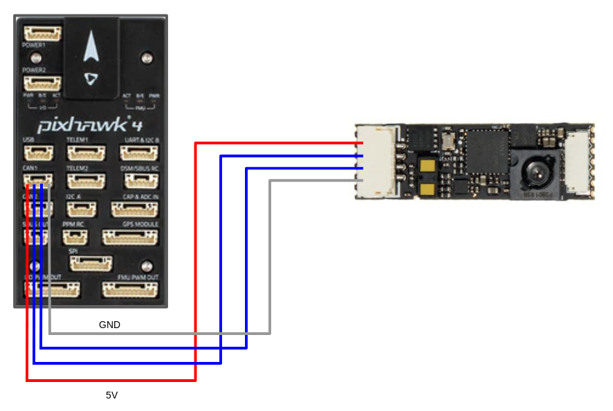
In addition to any other configuration, you will need to set the parameter UAVCAN_ENABLE to either 2 or 3, depending on your system:
UAVCAN_ENABLE=2: UAVCAN sensors but no motor controllers.UAVCAN_ENABLE=3: UAVCAN sensors and motor controllers.
For general information about UAVCAN wiring and configuration see: UAVCAN Peripherals.
# Thone ThoneFlow-3901U
The Thone ThoneFlow-3901U (opens new window) exposes a PMW3901 optical flow module via a UART interface.
The board doesn't include a distance sensor onboard, so you will need to use an external distance sensor.
PX4 configuration and mounting/orientation instructions are provided above.
In addition, you must also set the parameter SENS_TFLOW_CFG to the value of the UART port you connected (e.g. if the sensor is connected to TELEM 2 then set SENS_TFLOW_CFG=102. For more information see Serial Port Configuration.
← PX4光流 PWM 电调和伺服系统 →