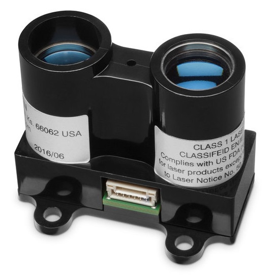
Lidar-Lite
LIDAR-Lite is a compact, high-performance optical distant measurement sensor solution for drone, robot or unmanned vehicle applications. It can be connected to either I2C or PWM.
Where to Buy
- LIDAR-Lite v3 (5cm - 40m)
Pinouts
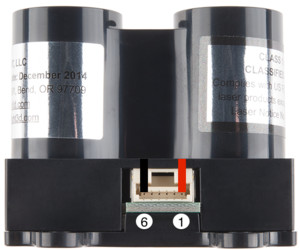
The Lidar-Lite (v2, v3) pinout is shown below.
| Pin | Name | Description |
|---|---|---|
| 1 | POWER_IN | Power supply. 4.75-5.5V DC Nominal, Maximum 6V DC. |
| 2 | POWER_EN | Active high, enables operation of the 3.3V micro-controller regulator. Low puts board to sleep, draws <40 μA. (Internal 100K pull-up) |
| 3 | Mode Select Control | Provides trigger (high-low edge) PWM out (high) |
| 4 | SCL | I2C Clock |
| 5 | SDA | I2C Data |
| 6 | GND | Signal/power ground. |
Wiring
The Lidar-Lite v3 can be used with either PWM or I2C. PWM is recommended if using an older model. The rangefinder must be separately powered via some ESC/BEC (whether connected via PWM or I2C).
The I2C interface of non-blue-label Lidar-Lite (v1) devices has stability limitations and all silver-label generations of Lidar-Lite sensors are therefore excluded from the I2C interface. The use of the PWM interface (as detailed below) is advised for these sensors. The blue label (v2) devices can exhibit a constant offset if powered on with less than 5V under some conditions. This is currently (Q4/2015) under investigation by the manufacturer and potentially can be resolved by adhering to specific operational conditions. The recommended robust setup is a v1 device interfaced via PWM.
The standard wiring instructions for Lidar-Lite 3 (from the Operation Manual) are shown below. Lidar-Lite v2 and v3 are the same, except that the order of pins in the connector is reversed (i.e. it is as though the connector was turned over).
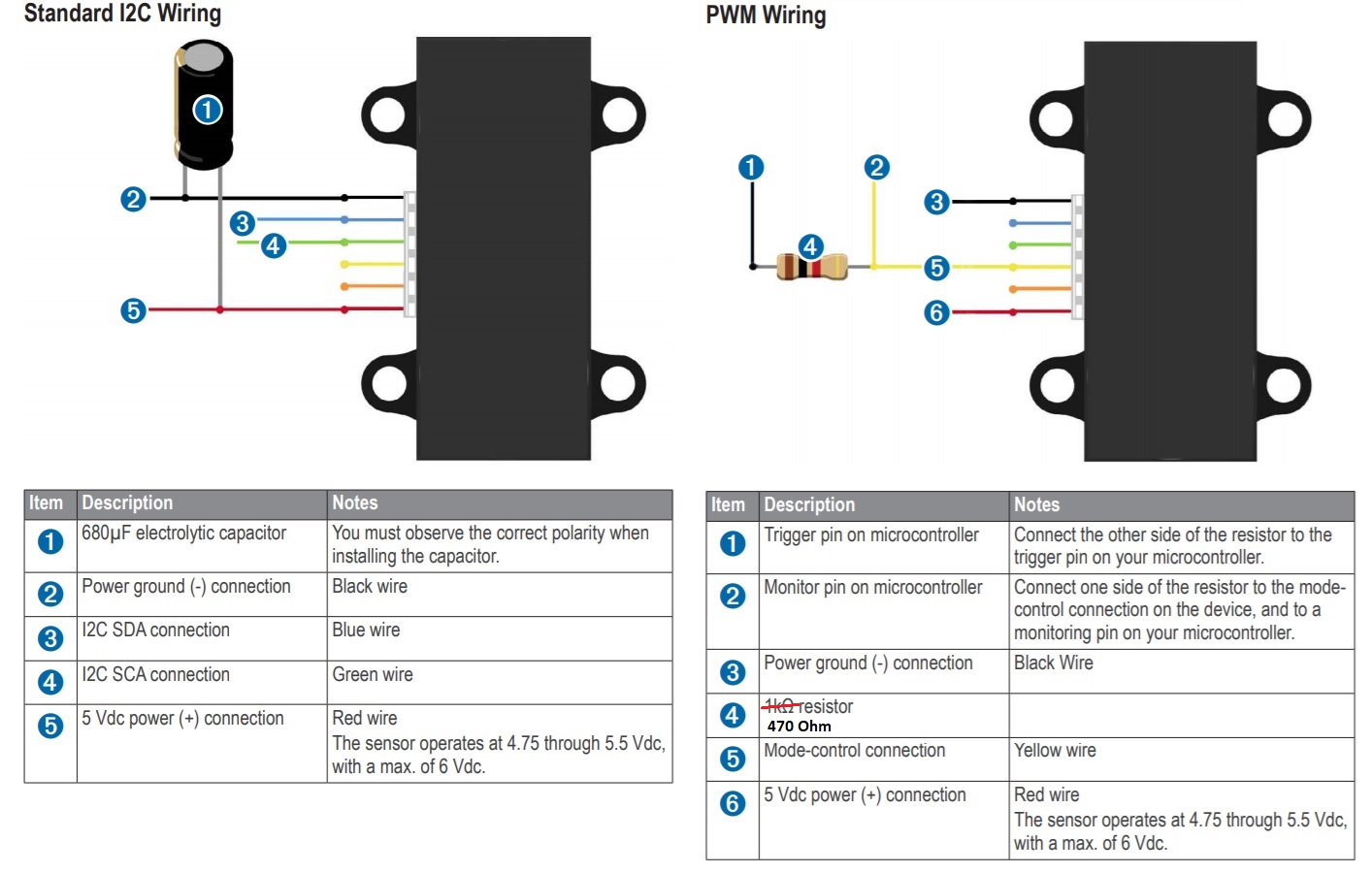
PWM Interface Wiring
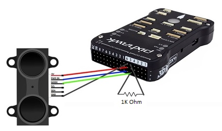
The pin connections for wiring LidarLite to the Pixhawk 1 AUX ports (PWM interface) are shown below.
| Pin | Lidar-Lite (v2, v3) | Pixhawk AUX Servo | Comment |
|---|---|---|---|
| 1 | VCC | AUX 6 (center) | Power supply. 4.75-5.5V DC Nominal, Maximum 6V DC. |
| 2 | RESET | AUX 6 (bottom) | Reset line of the sensor |
| 3 | PWM | AUX 5 (bottom) | PWM input of the Lidar Lite. Needs a 470 Ohm pull-down (to GND), Do not use a 1 K0hm resistor. |
| 4 | SCL | - | Not connected |
| 5 | SDA | - | Not connected |
| 6 | GND | AUX 6 (top) | Ground |
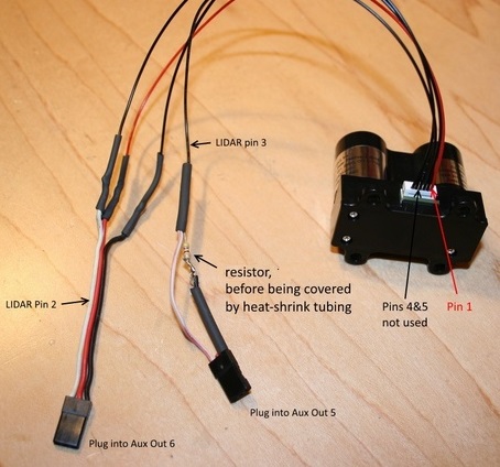
The wiring for LidarLite v2 is shown below. Lidar-Lite v3 is wired similarly, except that the pin-numbering on the connector is reversed.
I2C Interface Wiring
TBD
Software Configuration
The rangefinder/port is enabled using SENS_EN_LL40LS - set to 1 for PWM, or 2 for I2C.
The driver for this rangefinder is usually present in firmware. If missing, you would also need to add the driver (
drivers/ll40ls) to the board configuration.