# PX4 参考飞行控制器设计
PX4 参考设计是飞行控制器的 Pixhawk 系列 。 该设计于2011年首次发布,现已进入第5 代(第六代电路板设计正在进行中)。
# 二进制兼容性
所有按照特定设计制造的主板预计与二进制兼容(即可以运行相同的固件)。 从2018年起,我们将提供一个二进制兼容性测试套件,使我们能够验证兼容性。
第1-3代 FMU 设计用于开源硬件,但到了第4-5代只提供 pin 输出引脚和供电规格(原理图由个人开发者生成)。 为了可以更好的确保兼容性,FMUv6 及更新的版本重新提供完整的设计模型。
# 参考设计迭代:
- FMUv1:开发板 \(STM32F407, 128 KB RAM, 1MB flash, 原理图 (opens new window)\)(PX4 不再支持)
- FMUv2:Pixhawk \(STM32F427, 168 MHz, 192 KB RAM, 1MB flash, 原理图 (opens new window)\)
- FMUv3:2MB Flash 的 Pixhawk 变种 \(3DR Pixhawk 2 \(Solo\), Hex Pixhawk 2.1,Holybro Pixfalcon,3DR Pixhawk Mini,STM32F427,168 MHz,256 KB RAM,2 MB flash,原理图 (opens new window)\)
- FMUv4:Pixracer \(STM32F427, 168 MHz, 256 KB RAM, 2MB flash, 原理图 (opens new window)\)
- FMUv4 PRO: Drotek Pixhawk 3 PRO (STM32F469, 180 MHz, 384 KB RAM, 2 MB flash, 输出引脚 (opens new window))
- FMUv5: Holybro Pixhawk 4 (STM32F765, 216 MHz, 512 KB RAM, 2 MB flash, 输出引脚 (opens new window))
- FMUv6:尚未完成,最终命名为 TBD,变种 6s (STM32H7, 400 MHz, 2 MB RAM, 2 MB flash) 和变种 6i (i.MX RT1050, 600 MHz, 512 KB RAM, 外部 flash)
# Main/IO 功能分解
下图展示了在Pixhawk系列飞行控制器(这些板被合并进一个单独的物理模块中)中 FMU 和 I/O 板之间总线和功能的职能划分。
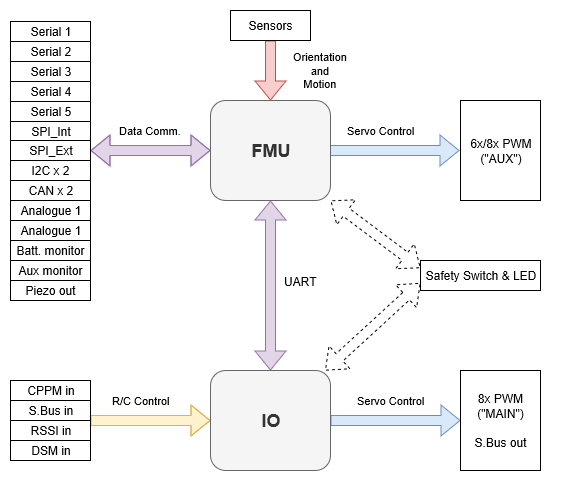
一些Pixhawk系列控制器为了减少空间或复杂性,或者更好解决使用问题,没有通过I/O板构建。
I/O 板被设置参数 SYS_USE_IO=0 禁用。 当I/O 板被禁用时:
- 主混合器文件被加载到FMU(所以列在机型参考的“主”输出出现在标有AUX的端口上) AUX 混合器不被加载,所以定义在文件中的输出不会使用。
- 遥控输出不通过IO板,而是直接连接在FMU上。
没有I/O板的飞行控制器有MAIN端口,但是它们没有AUX端口。 因此,他们只能在哪些不使用AUX端口或者使用非必要途径(例如 遥控直通)的机型使用。 They can be used for most multicopters and fully autonomous vehicles (without a safety pilot using RC control), as these typically only use MAIN ports for motors/essential controls.
注意
Flight controllers without an I/O board cannot be used in airframes that map any AUX ports to essential flight controls or motors (as they have no AUX ports).
注解
Manufacturer flight controller variants without an I/O board are often named as a "diminutive" of a version that includes the I/O board: e.g. Pixhawk 4 Mini_, CUAV v5 nano.
Most PX4 PWM outputs are mapped to either MAIN or AUX ports in mixers. A few specific cases, including camera triggering and Dshot ESCs, are directly mapped to the FMU pins (i.e. they will output to either MAIN or AUX, depending on whether or not the flight controller has an I/O board).
← 硬件仿真 制造商的版面支持指南 →