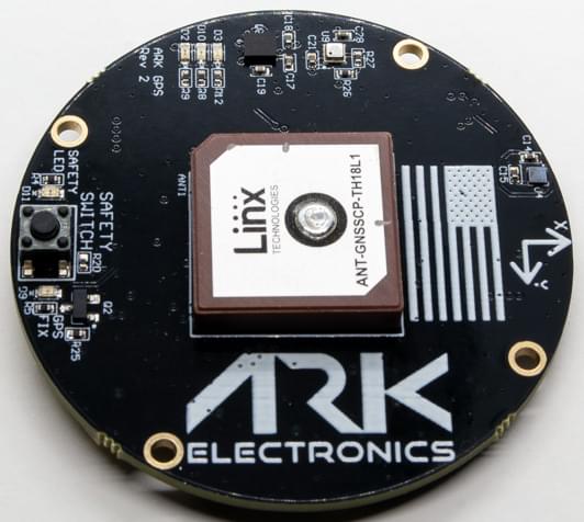
# ARK GPS
ARK GPS is an open source DroneCAN GNSS/GPS, magnetometer, IMU, barometer, buzzer, and safety switch module.

# Where to Buy
Order this module from:
# Hardware Specifications
- Open Source Schematic and BOM (opens new window)
- Sensors
- Ublox M9N GPS
- Ultra-robust meter-level GNSS positioning
- Maximum position availability with concurrent reception of 4 GNSS
- Advanced spoofing and jamming detection
- Excellent RF interference mitigation
- Bosch BMM150 Magnetometer
- Bosch BMP388 Barometer
- Invensense ICM-42688-P 6-Axis IMU
- Ublox M9N GPS
- STM32F412CEU6 MCU
- Safety Button
- Buzzer
- Two Pixhawk Standard CAN Connectors (4 Pin JST GH)
- Pixhawk Standard Debug Connector (6 Pin JST SH)
- Small Form Factor
- 5cm x 5cm x 1cm
- LED Indicators
- Safety LED
- GPS Fix
- RGB System Status
- USA Built
- Power Requirements
- 5V
- 110mA Average
- 117mA Max
# Hardware Setup
# Wiring
The ARK GPS is connected to the CAN bus using a Pixhawk standard 4 pin JST GH cable. For more information, refer to the CAN Wiring instructions.
# Mounting
The recommended mounting orientation is with the connectors on the board pointing towards the back of vehicle.
The sensor can be mounted anywhere on the frame, but you will need to specify its position, relative to vehicle centre of gravity, during PX4 configuration.
# Firmware Setup
ARK GPS runs the PX4 DroneCAN Firmware. As such, it supports firmware update over the CAN bus and dynamic node allocation.
ARK GPS boards ship with recent firmware pre-installed, but if you want to build and flash the latest firmware yourself see PX4 DroneCAN Firmware > Building the Firmware.
- Firmware target:
ark_can-gps_default - Bootloader target:
ark_can-gps_canbootloader
# PX4 Configuration
You need to set necessary DroneCAN parameters and define offsets if the sensor is not centred within the vehicle. The required settings are outlined below.
Note
The ARK GPS will not boot if there is no SD card in the flight controller when powered on.
# Enable DroneCAN
In order to use the ARK GPS board, connect it to the Pixhawk CAN bus and enable the DroneCAN driver by setting parameter UAVCAN_ENABLE to 2 for dynamic node allocation (or 3 if using DroneCAN ESCs).
The steps are:
- In QGroundControl set the parameter UAVCAN_ENABLE to
2or3and reboot (see Finding/Updating Parameters). - Connect ARK GPS CAN to the Pixhawk CAN.
Once enabled, the module will be detected on boot. GPS data should arrive at 10Hz.
DroneCAN configuration in PX4 is explained in more detail in DroneCAN > Enabling DroneCAN.
# Sensor Position Configuration
If the sensor is not centred within the vehicle you will also need to define sensor offsets:
- Enable GPS yaw fusion by setting bit 3 of EKF2_GPS_CTRL to true.
- Enable UAVCAN_SUB_GPS, UAVCAN_SUB_MAG, and UAVCAN_SUB_BARO.
- Set CANNODE_TERM to
1if this is that last node on the CAN bus. - The parameters EKF2_GPS_POS_X, EKF2_GPS_POS_Y and EKF2_GPS_POS_Z can be set to account for the offset of the ARK GPS from the vehicles centre of gravity.
# LED Meanings
You will see green, blue and red LEDs on the ARK GPS when it is being flashed, and a blinking green LED if it is running properly.
If you see a red LED there is an error and you should check the following:
- Make sure the flight controller has an SD card installed.
- Make sure the ARK GPS has
ark_can-gps_canbootloaderinstalled prior to flashingark_can-gps_default. - Remove binaries from the root and ufw directories of the SD card and try to build and flash again.