# Multicopter PID Tuning Guide
This tutorial explains how to tune the PID loops on PX4 for all multicopter setups (Quads, Hexa, Octo etc).
Tuning is recommended for all new vehicle setups, because relatively small hardware and assembly changes can affect the gains required tuning gains for optimal flight. For example, different ESCs or motors require different tuning gains.
TIP
Generally if you're using an appropriate supported airframe configuration (selected from QGroundControl > Airframe), the default tuning should allow you to fly the vehicle safely. To get the very best performance we recommend you tune your new vehicle.
WARNING
Poorly tuned vehicles are likely to be unstable, and easy to crash. Make sure to have assigned a Kill switch.
# Introduction
PX4 uses Proportional, Integral, Derivative (PID) controllers (these are the most widespread control technique).
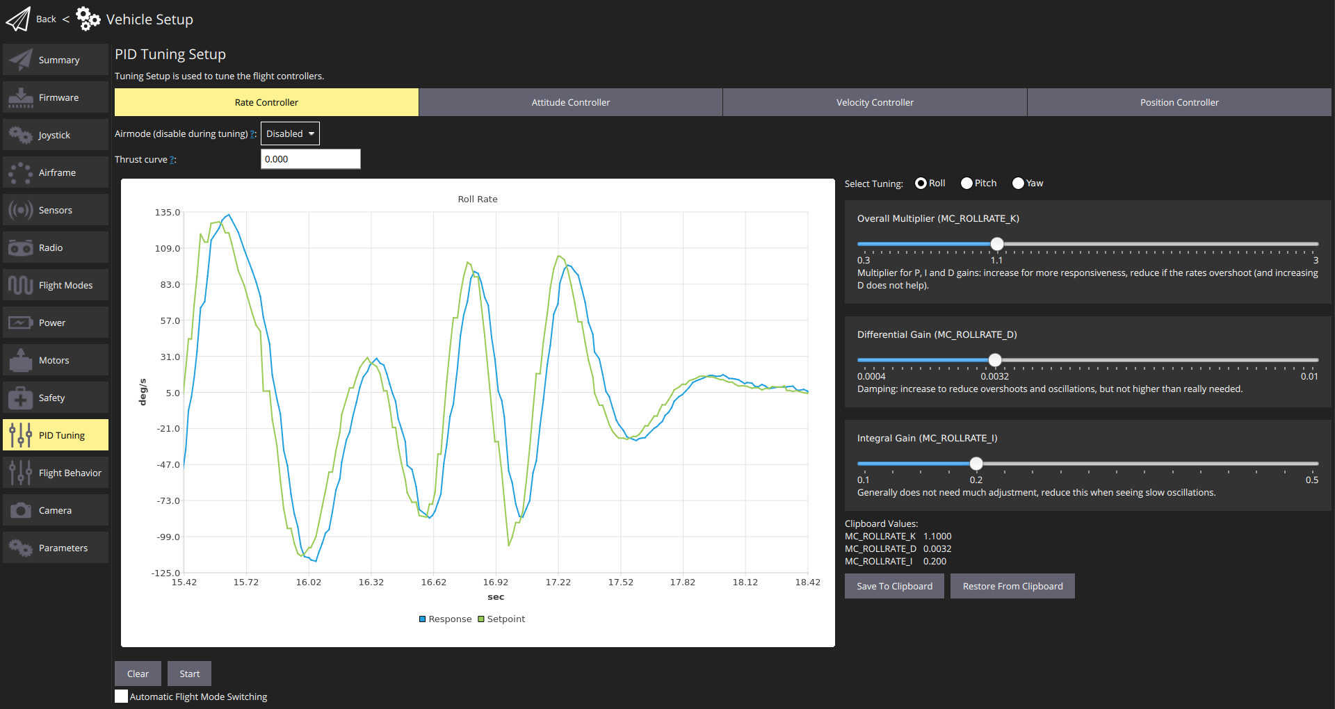
The QGroundControl PID Tuning setup provides real-time plots of the vehicle setpoint and response curves. The goal of tuning is to set the P/I/D values such that the Response curve matches the Setpoint curve as closely as possible (i.e. a fast response without overshoots).
The controllers are layered, which means a higher-level controller passes its results to a lower-level controller. The lowest-level controller is the rate controller, followed by the attitude controller, and finally the velocity & position controller. The PID tuning needs to be done in this same order, starting with the rate controller, as it will affect all other controllers.
The testing procedure for each controller (rate, attitude, velocity/posibition) and axis (yaw, roll, pitch) is always the same: create a fast setpoint change by moving the sticks very rapidly and observe the response. Then adjust the sliders (as discussed below) to improve the tracking of the response to the setpoint.
TIP
- Rate controller tuning is the most important, and if tuned well, the other controllers often need no or only minor adjustments
- Usually the same tuning gains can be used for roll and pitch.
- use Acro/Stabilized/Altitude mode to tune the rate controller
- Use Position mode to tune the Velocity Controller and the Position Controller.
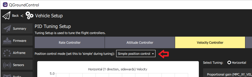
Make sure to switch to the Simple position control mode so you can generate step inputs.
# Preconditions
You are using the QGroundControl daily build (opens new window) (the latest tuning UI will be in the next release build after March 2021).
You have selected the closest matching default airframe configuration for your vehicle. This should give you a vehicle that already flies.
You should have done an ESC calibration.
If using PWM output: PWM_MAIN_MIN is set correctly. It needs to be set low, but such that the motors never stop when the vehicle is armed.
This can be tested in Acro mode or in Manual/Stabilized mode:
- Remove propellers
- Arm the vehicle and lower the throttle to the minimum
- Tilt the vehicle to all directions, about 60 degrees
- Check that no motors turn off
Use a high-rate telemetry link such as WiFi if at all possible (a typical low-range telemetry radio is not fast enough for real-time feedback and plots). This is particularly important for the rate controller.
Disable MC_AIRMODE before tuning a vehicle (there is an options for this in the PID tuning screen).
# Tuning Procedure
The tuning procedure is:
Arm the vehicle, takeoff, and hover (typically in Position mode).
Open QGroundControl Vehicle Setup > PID Tuning
Select the Rate Controller tab.
Confirm that the airmode selector is set to Disabled
Set the Thrust curve value to: 0.3 (PWM, power-based controllers) or 1 (RPM-based ESCs)
Note
For PWM, power-based and (some) UAVCAN speed controllers, the control signal to thrust relationship may not be linear. As a result, the optimal tuning at hover thrust may not be ideal when the vehicle is operating at higher thrust.
The thrust curve value can be used to compensate for this non-linearity:
- For PWM controllers, 0.3 is a good default (which may benefit from further tuning).
- For RPM-based controllers, use 1 (no further tuning is required as these have a quadratic thrust curve).
For more information see the detailed PID tuning guide.
Set the Select Tuning radio button to: Roll.
(Optionally) Select the Automatic Flight Mode Switching checkbox. This will automatically switch from Position mode to Stabilised mode when you press the Start button
For rate controller tuning switch to Acro mode, Stabilized mode or Altitude mode (unless automatic switching is enabled).
Select the Start button in order to start tracking the setpoint and response curves.
Rapidly move the roll stick full range and observe the step response on the plots.
TIP
Stop tracking to enable easier inspection of the plots. This happens automatically when you zoom/pan. Use the Start button to restart the plots, and Clear to reset them.
Modify the three PID values using the sliders (for roll rate-tuning these affect
MC_ROLLRATE_K,MC_ROLLRATE_I,MC_ROLLRATE_D) and observe the step response again. The values are saved to the vehicle as soon as the sliders are moved.Note
The goal is for the Response curve to match the Setpoint curve as closely as possible (i.e. a fast response without overshoots).
The PID values can be adjusted as follows:
- P (proportional) or K gain:
- increase this for more responsiveness
- reduce if the response is overshooting and/or oscillating (up to a certain point increasing the D gain also helps).
- D (derivative) gain:
- this can be increased to dampen overshoots and oscillations
- increase this only as much as needed, as it amplifies noise (and can lead to hot motors)
- I (integral) gain:
- used to reduce steady-state error
- if too low, the response might never reach the setpoint (e.g. in wind)
- if too high, slow oscillations can occur
- P (proportional) or K gain:
Repeat the tuning process above for the pitch and yaw:
- Use Select Tuning radio button to select the axis to tune
- Move the appropriate sticks (i.e. pitch stick for pitch, yaw stick for yaw).
- For pitch tuning, start with the same values as for roll.
TIP
Use the Save to Clipboard and Reset from Clipboard buttons to copy the roll settings for initial pitch settings.
Repeat the tuning process for the attitude controller on all the axes.
Repeat the tuning process for the velocity and positions controllers (on all the axes).
Use Position mode when tuning these controllers
Select the Simple position control option in the Position control mode ... selector (this allows direct control for the generation of step inputs)
All done! Remember to re-enable airmode before leaving the setup.