# 混控器和执行器
PX4 的系统构架可确保不需要在核心控制器中对不同的机身布局进行任何特殊的处理。
混合意味着接收力的指令(比如: 向右转),然后将这些指令转换成实际的执行器指令来控制电机或者舵机。 对于一个每片副翼都有一个舵机的飞机而言这就意味着控制这两个舵机一个向上偏转,一个向下偏转。 这也适用于多旋翼:向前俯仰需要改变所有电机的转速。
将混控逻辑与实际的姿态控制器分离开来大大提高了程序的可复用性。
# 控制通道
特定的控制器发送一个特定的归一化的力或力矩指令(缩放至 -1..+1 )给混控器,混控器则相应地去设置每个单独的执行器。 控制量输出驱动程序(比如:UART, UAVCAN 或者 PWM)则将混控器的输出所放为执行器实际运行时的原生单位, 例如输出一个值为 1300 的 PWM 指令。
# 控制组
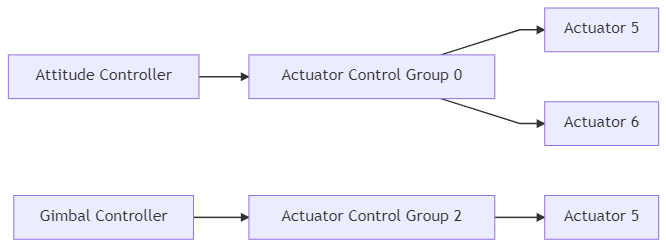
PX4 系统中使用控制组(输入)和输出组。 从概念上讲这两个东西非常简单: 一个控制组可以是核心飞行控制器的 姿态,也可以是载荷的 云台 。 一个输出组则是一个物理上的总线,例如 飞控上最开始的 8 个 PWM 舵机输出口。 每一个组都有 8 个单位化(-1..+1)的指令端口,这些端口可以通过混控器进行映射和缩放。 混控器定义了这 8 个控制信号如何连接至 8 个输出口。
对于一个简单的飞机来说 control 0(滚转)直接与 output 0(副翼)相连接。 对于多旋翼而言事情要稍有不同:control 0(滚转)与全部四个电机相连接,并会被整合至油门指令中。
# 控制组 #0 (Flight Control)
- 0:roll (-1..1)
- 1:pitch (-1..1)
- 2:yaw (-1..1)
- 3:throttle (正常范围为 0..1,变距螺旋桨和反推动力情况下范围为 -1..1)
- 4:flaps (-1..1)
- 5:spoilers (-1..1)
- 6:airbrakes (-1..1)
- 7:landing gear (-1..1)
# 控制组 #1 (Flight Control VTOL/Alternate)
- 0:roll ALT (-1..1)
- 1:pitch ALT (-1..1)
- 2:yaw ALT (-1..1)
- 3:throttle ALT (正常范围为 0..1,变距螺旋桨和反推动力情况下范围为 -1..1)
- 4:保留 / aux0
- 5:reserved / aux1
- 6:保留 / aux2
- 7:保留 / aux3
# 控制组 #2 (Gimbal)
- 0:gimbal roll
- 1:gimbal pitch
- 2: gimbal yaw
- 3: gimbal shutter
- 4:保留
- 5:保留
- 6:保留
- 7:保留 (降落伞, -1..1)
# 控制组 #3 (Manual Passthrough)
- 0: RC roll
- 1: RC pitch
- 2: RC yaw
- 3: RC throttle
- 4: RC mode switch
- 5: RC aux1
- 6: RC aux2
- 7: RC aux3
注解
This group is only used to define mapping of RC inputs to specific outputs during normal operation (see quad_x.main.mix (opens new window) for an example of AUX2 being scaled in a mixer). In the event of manual IO failsafe override (if the PX4FMU stops communicating with the PX4IO board) only the mapping/mixing defined by control group 0 inputs for roll, pitch, yaw and throttle are used (other mappings are ignored).
# 控制组 #6 (First Payload)
- 0: function 0 (默认:降落伞)
- 1: function 1
- 2: function 2
- 3: function 3
- 4: function 4
- 5: function 5
- 6: function 6
- 7: function 7
# 虚拟控制组
注意
Virtual Control Groups are only relevant to developers creating VTOL code. They should not be used in mixers, and are provided only for "completeness".
These groups are NOT mixer inputs, but serve as meta-channels to feed fixed wing and multicopter controller outputs into the VTOL governor module.
# 控制组 #4 (Flight Control MC VIRTUAL)
- 0:roll ALT (-1..1)
- 1:pitch ALT (-1..1)
- 2:yaw ALT (-1..1)
- 3: throttle ALT (正常范围为 0..1,变距螺旋桨和反推动力情况下范围为 -1..1)
- 4:保留 / aux0
- 5:保留 / aux1
- 6:保留 / aux2
- 7:保留 / aux3
# 控制组 #5 (Flight Control FW VIRTUAL)
- 0:roll ALT (-1..1)
- 1: pitch ALT (-1..1)
- 2: yaw ALT (-1..1)
- 3: throttle ALT (正常范围为 0..1,变距螺旋桨和反推动力情况下范围为 -1..1)
- 4:保留 / aux0
- 5:保留 / aux1
- 6:保留 / aux2
- 7:保留 / aux3
# 映射
因为有多个控制组(例如飞行控制、有效载荷等)。 和多个输出组(总线) ,一个控制组可以向多个输出组发送命令。
The mixer file does not explicitly define the actual output group (physical bus) where the outputs are applied. Instead, the purpose of the mixer (e.g. to control MAIN or AUX outputs) is inferred from the mixer filename, and mapped to the appropriate physical bus in the system startup scripts (and in particular in rc.interface (opens new window)).
注解
This approach is needed because the physical bus used for MAIN outputs is not always the same; it depends on whether or not the flight controller has an IO Board (see PX4 Reference Flight Controller Design > Main/IO Function Breakdown) or uses UAVCAN for motor control. The startup scripts load the mixer files into the appropriate device driver for the board, using the abstraction of a "device". The main mixer is loaded into device /dev/uavcan/esc (uavcan) if UAVCAN is enabled, and otherwise /dev/pwm_output0 (this device is mapped to the IO driver on controllers with an I/O board, and the FMU driver on boards that don't). The aux mixer file is loaded into device /dev/pwm_output1, which maps to the FMU driver on Pixhawk controllers that have an I/O board.
Since there are multiple control groups (like flight controls, payload, etc.) and multiple output groups (buses), one control group can send commands to multiple output groups.

注解
In practice, the startup scripts only load mixers into a single device (output group). This is a configuration rather than technical limitation; you could load the main mixer into multiple drivers and have, for example, the same signal on both UAVCAN and the main pins.
# PX4 混控器定义
Mixers are defined in plain-text files using the syntax below.
Files for pre-defined airframes can be found in ROMFS/px4fmu_common/mixers (opens new window). These can be used as a basis for customisation, or for general testing purposes.
# 混控器描述文件命名
空的混控器使用如下形式定义:
# 语法
The default set of mixer files (in PX4 firmware) are defined in px4fmu_common/init.d/airframes/ (opens new window). These can be overridden by mixer files with the same name in the SD card directory /etc/mixers/ (SD card mixer files are loaded by preference).
PX4 loads mixer files named XXXX.main.mix onto the MAIN outputs and YYYY.aux.mix onto the AUX outputs, where the prefixes depend on the airframe and airframe configuration. Commonly the MAIN and AUX outputs correspond to MAIN and AUX PWM outputs, but these may be loaded into a UAVCAN (or other) bus when that is enabled.
The MAIN mixer filename (prefix XXXX) is set in the airframe configuration using set MIXER XXXX (e.g. airframes/10015_tbs_discovery (opens new window) calls set MIXER quad_w to load the main mixer file quad_w.main.mix).
The AUX mixer filename (prefix YYYY above) depends on airframe settings and/or defaults:
- 4x - X 构型的四旋翼
- Multicopter and Fixed-Wing airframes load pass.aux.mix (opens new window) by default (i.e if not set using
MIXER_AUX). :::tippass.aux.mixis the RC passthrough mixer, which passes the values of 4 user-defined RC channels (set using the RC_MAP_AUXx/RC_MAP_FLAPS parameters) to the first four outputs on the AUX output. ::: - VTOL frames load the AUX file specified using
MIXER_AUXif set, or the value specified byMIXERif not. - 6+ - + 构型的六旋翼
注解
Mixer file loading is implemented in ROMFS/px4fmu_common/init.d/rc.interface (opens new window).
# Loading a Custom Mixer
PX4 loads appropriately named mixer files from the SD card directory /etc/mixers/, by preference, and then the version in Firmware.
To load a custom mixer, you should give it the same name as a "normal" mixer file (that is going to be loaded by your airframe) and put it in the etc/mixers directory on your flight controller's SD card.
Most commonly you will override/replace the AUX mixer file for your current airframe (which may be the RC passthrough mixer - pass.aux.mix (opens new window)). See above for more information on mixer loading.
提示
You can also manually load a mixer at runtime using the mixer load command (thereby avoiding the need for a reboot). For example, to load a mixer /etc/mixers/test_mixer.mix onto the MAIN PWM outputs, you could enter the following command in a console:
<tag>: <mixer arguments>
多旋翼的混控器将四组控制输入(俯仰、滚转、偏航和推力)整合到一组用于驱动电机转速控制器的执行器输出指令中。
# 语法
该混控器使用如下形式的行进行定义:
There are four types of mixers definitions: multirotor mixer, helicopter mixer, summing mixer, and null mixer.
- Multirotor mixer - Defines outputs for 4, 6, or 8 rotor vehicles with + or X geometry.
- Helicopter mixer - Defines outputs for helicopter swash-plate servos and main motor ESCs (the tail-rotor is a separate summing mixer.)
- 一个简单的混控器会将零个或者多个控制输入组合成一个执行器输出。 控制输入首先会被缩放,然后混合函数在进行输出缩放时会对结果进行求和。
- Null mixer - Generates a single actuator output that has zero output (when not in failsafe mode).
提示
Use multirotor and helicopter mixers for the respective types, the summing mixer for servos and actuator controls, and the null mixer for creating outputs that must be zero during normal use (e.g. a parachute has 0 normally, but might have a particular value during failsafe). A VTOL Mixer combines the other mixer types.
The number of outputs generated by each mixer depends on the mixer type and configuration. For example, the multirotor mixer generates 4, 6, or 8 outputs depending on the geometry, while a summing mixer or null mixer generate just one output.
上面的第二行还使用在之前讨论中提到的缩放参数对输出缩放器进行了定义。 同时,结果的计算是以浮点计算的形式进行的,在混控器定义文件中的值都将缩小 10000 倍,比如:实际中 -0.5 的偏移量(offset)在定义文件中保存为 -5000 。 For example, if you define a multi-rotor mixer for a quad geometry, followed by a null mixer, followed by two summing mixers then this would allocate the first 4 outputs to the quad, an "empty" output, and the next two outputs.
当有一个执行器出现饱和后,所有执行器的值都将被重新缩放以使得饱和执行器的输出被限制在 1.0 。
M: <control count>
O: <-ve scale> <+ve scale> <offset> <lower limit> <upper limit>
The tag selects the mixer type (see links for detail on each type):
当将混控器用于混合飞机的控制量时,编号为 0 的混控器组为飞机的姿态控制组,该控制组内编号 0 - 3 的选项通常分别便是滚转、俯仰、偏航和推力。
剩下的字段则是使用上文提及的缩放参数对控制量的缩放器进行了设定。 同时,结果的计算是以浮点计算的形式进行的,在混控器定义文件中的值都将缩小 10000 倍,比如:实际中 -0.5 的偏移量(offset)在定义文件中保存为 -5000 。
# 空的混控器(Null)
这里 是一个典型混控器的示例文件。
A summing (simple) mixer combines zero or more control inputs into a single actuator output. Inputs are scaled, and the mixing function sums the result before applying an output scaler. A minimal actuator traversal time limit can also be specified in the output scaler (inverse of a slew rate).
A simple mixer definition begins with:
S: <group> <index> <-ve scale> <+ve scale> <offset> <lower limit> <upper limit>
空的混控器使用如下形式定义:
The second line defines the output scaler with scaler parameters as discussed above. While the calculations are performed as floating-point operations, the values stored in the definition file are scaled by a factor of 10000; i.e. an offset of -0.5 is encoded as -5000. The <traversal time> (optional) on the output scaler is intended for actuators that may be damaged if they move too fast — like the tilting actuators on a tiltrotor VTOL vehicle. It can be used to limit the rate of change of an actuator (if this is not specified then no rate limit is applied). For example, a <traversal time> value of 20000 will limit the rate of change of the actuator such that it takes at least 2 seconds from the <lower limit> to the <upper limit> and vice versa.
该混控器使用如下形式的行进行定义:
- 6x - X 构型的六旋翼
- Do not apply any limit on actuators controlling the attitude of a vehicle (such as servos for the aerodynamic surfaces), as this could easily lead to controller instability. :::
The definition continues with <control count> entries describing the control inputs and their scaling, in the form:
Z:
滚转、俯仰和偏航的缩放因子大小都分别表示滚转、俯仰和边行控制相对于推力控制的比例。 同时,结果的计算是以浮点计算的形式进行的,在混控器定义文件中的值都将缩小 10000 倍,比如:实际中 0.5 的偏移量(offset)在定义文件中保存为 5000 。
注解
Any mixer output that has a throttle input (an S:-line with <group>=0 and <index>=3) won't work in disarmed or prearmed state. For example, a servo that has four inputs (roll, pitch, yaw and throttle) won't move in disarmed state even with roll/pitch/yaw signals.
The <group> value identifies the control group from which the scaler will read, and the <index> value an offset within that group. These values are specific to the device reading the mixer definition.
When used to mix vehicle controls, mixer group zero is the vehicle attitude control group, and index values zero through three are normally roll, pitch, yaw and thrust respectively.
The remaining fields on the line configure the control scaler with parameters as discussed above. Whilst the calculations are performed as floating-point operations, the values stored in the definition file are scaled by a factor of 10000; i.e. an offset of -0.5 is encoded as -5000.
An example of a typical mixer file is explained here.
# 一个简单的混控器
A null mixer consumes no controls and generates a single actuator output with a value that is always zero.
Typically a null mixer is used as a placeholder in a collection of mixers in order to achieve a specific pattern of actuator outputs. It may also be used to control the value of an output used for a failsafe device (the output is 0 in normal use; during failsafe the mixer is ignored and a failsafe value is used instead).
后面的各行则是对每个倾斜盘舵机( 3 个或者 4 个)进行设定,文本行的形式如下:
R: <geometry> <roll scale> <pitch scale> <yaw scale> <idlespeed>
# 针对多旋翼的混控器
The multirotor mixer combines four control inputs (roll, pitch, yaw, thrust) into a set of actuator outputs intended to drive motor speed controllers.
The mixer definition is a single line of the form:
H: <number of swash-plate servos, either 3 or 4>
T: <throttle setting at thrust: 0%> <25%> <50%> <75%> <100%>
P: <collective pitch at thrust: 0%> <25%> <50%> <75%> <100%>
The supported geometries include:
- 它的油门曲线刚开始时斜率很陡,在 50% 油门位置便达到了 6000(0.6)。
- 随后油门曲线会以一个稍平缓的斜率实现在 100% 油门位置时到达 10000(1.0)。
- 总距曲线是线性的,但没有用到全部的控制指令区间。
- 0% 油门位置时总距设置就已经是 500(0.05)了。
- 油门处于最大位置时总距仅仅为 4500(0.45)。
- 对于该型直升机而言使用更高的值会导致主桨叶失速。
完成上述工作后,直升机的尾桨设定直接映射到了飞机的偏航指令上。 该设置同时适用于舵机控制的尾桨和使用专用电机控制的尾桨。
Roll, pitch and yaw inputs are expected to range from -1.0 to 1.0, whilst the thrust input ranges from 0.0 to 1.0. Output for each actuator is in the range -1.0 to 1.0.
Idlespeed can range from 0.0 to 1.0. Idlespeed is relative to the maximum speed of motors and it is the speed at which the motors are commanded to rotate when all control inputs are zero.
In the case where an actuator saturates, all actuator values are rescaled so that the saturating actuator is limited to 1.0.
# 针对直升机的混控器
The helicopter mixer combines three control inputs (roll, pitch, thrust) into four outputs (swash-plate servos and main motor ESC setting). The first output of the helicopter mixer is the throttle setting for the main motor. The subsequent outputs are the swash-plate servos. The tail-rotor can be controlled by adding a simple mixer.
The thrust control input is used for both the main motor setting as well as the collective pitch for the swash-plate. It uses a throttle-curve and a pitch-curve, both consisting of five points.
注解
The throttle- and pitch- curves map the "thrust" stick input position to a throttle value and a pitch value (separately). This allows the flight characteristics to be tuned for different types of flying. An explanation of how curves might be tuned can be found in this guide (opens new window) (search on Programmable Throttle Curves and Programmable Pitch Curves).
The mixer definition begins with:
S: <angle> <arm length> <scale> <offset> <lower limit> <upper limit>
T: defines the points for the throttle-curve. P: defines the points for the pitch-curve. Both curves contain five points in the range between 0 and 10000. For simple linear behavior, the five values for a curve should be 0 2500 5000 7500 10000.
This is followed by lines for each of the swash-plate servos (either 3 or 4) in the following form:
M: 1
S: 0 2  10000  10000      0 -10000  10000
The <angle> is in degrees, with 0 degrees being in the direction of the nose. Viewed from above, a positive angle is clock-wise. The <arm length> is a normalized length with 10000 being equal to 1. If all servo-arms are the same length, the values should al be 10000. A bigger arm length reduces the amount of servo deflection and a shorter arm will increase the servo deflection.
The servo output is scaled by <scale> / 10000. After the scaling, the <offset> is applied, which should be between -10000 and +10000. The <lower limit> and <upper limit> should be -10000 and +10000 for full servo range.
The tail rotor can be controller by adding a summing mixer:
M: 1
S: 0 2  10000  10000      0 -10000  10000
By doing so, the tail rotor setting is directly mapped to the yaw command. This works for both servo-controlled tail-rotors, as well as for tail rotors with a dedicated motor.
The blade 130 helicopter mixer (opens new window) can be viewed as an example.
H: 3
T:      0   3000   6000   8000  10000
P:    500   1500   2500   3500   4500
# Swash plate servos:
S:      0  10000  10000      0  -8000   8000
S:    140  13054  10000      0  -8000   8000
S:    220  13054  10000      0  -8000   8000

# Tail servo:
M: 1
S: 0 2  10000  10000      0 -10000  10000
- The throttle-curve starts with a slightly steeper slope to reach 6000 (0.6) at 50% thrust.
- It continues with a less steep slope to reach 10000 (1.0) at 100% thrust.
- The pitch-curve is linear, but does not use the entire range.
- At 0% throttle, the collective pitch setting is already at 500 (0.05).
- At maximum throttle, the collective pitch is only 4500 (0.45).
- Using higher values for this type of helicopter would stall the blades.
- The swash-plate servos for this helicopter are located at angles of 0, 140 and 220 degrees.
- The servo arm-lenghts are not equal.
- The second and third servo have a longer arm, by a ratio of 1.3054 compared to the first servo.
- The servos are limited at -8000 and 8000 because they are mechanically constrained.
# VTOL 混控器
VTOL systems use a multirotor mixer for the multirotor outputs, and summing mixers for the fixed-wing actuators (and the tilting servos in case of a tiltrotor VTOL).
The mixer system for a VTOL vehicle can be either combined into a single mixer, where all the actuators are connected to either the IO or the FMU port, or split into separate mixer files for IO and for AUX. If separated, we recommend that all the multicopter motors are on one port, and all the servos and the fixed-wing motor on the other.
注解
The FMU output can only be used for multirotor motors starting from PX4 v1.11. To use the FMU output set VT_MC_ON_FMU=1 (otherwise they are not switched off when in fixed-wing flight mode).