# RTPS/ROS2 接口:PX4-FastRTPS桥接
The PX4-Fast RTPS(DDS) Bridge, which is also referred to as as the microRTPS Bridge, adds a Real Time Publish Subscribe (RTPS) interface to the PX4 Autopilot, enabling the exchange of uORB messages between the various PX4 Autopilot internal components and (offboard) Fast DDS applications in realtime.
This allows us to better integrate with applications running and linked in DDS domains (including ROS nodes), making it easy to share sensor data, commands, and other vehicle information.
The following guide describes the RTPS/DDS bridge architecture, and shows the reader how to write a simple Fast DDS application to subscribe to telemetry updates from the PX4 Autopilot.
当您需要在飞行控制器和offboard部件之间可靠地共享时间敏感/实时信息时, 应使用RTPS。 特别是, 在off-board软件需要 (通过发送和接收 uORB主题) 成为 px4 中运行的软件组件的 伙伴 的情况下,它非常有用。
Fast DDS is a very lightweight cross-platform implementation of the latest version of the RTPS protocol / DDS middleware. It was previously named Fast RTPS. :::
# 什么时候应该使用 RTPS?
RTPS should be used when you need to reliably share time-critical/real-time information between the flight controller and offboard components. It is instrumental in cases where offboard software needs to become a peer of software components running in PX4 (sending and receiving uORB topics).
Possible use cases include communicating with robotics libraries for computer vision and other use cases where real-time data to/from actuators and sensors is essential for vehicle control.
Fast DDS is not intended as a replacement for MAVLink. MAVLink remains the most appropriate protocol for communicating with ground stations, gimbals, cameras, and other offboard components (although Fast DDS may open other opportunities for working with some peripherals at higher frequencies).
提示
It is possible to use Fast RTPS(DDS) over slower links (e.g., radio telemetry) by being mindful of your link's extra constraints. Keep in mind you can easily overload your telemetry channel.
# 架构概述
# RTPS 桥接
The microRTPS bridge exchanges messages between PX4 and DDS-participant applications, seamlessly converting between the uORB and RTPS/DDS messages used by each system.
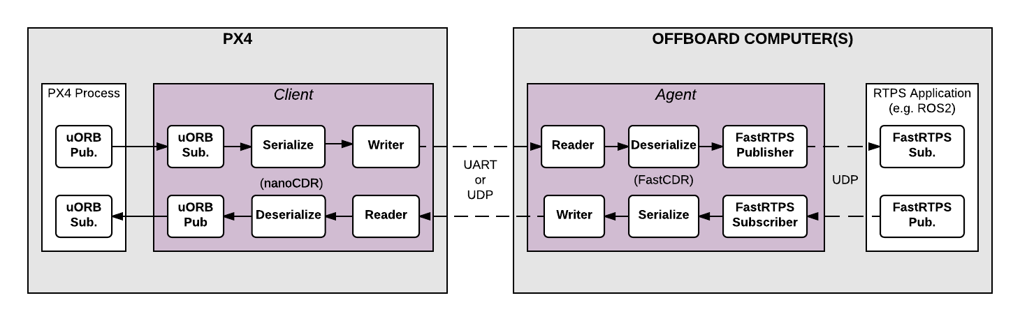
The main elements of the architecture are the client and agent processes shown in the diagram above.
# The microRTPS Client
The Client is the PX4 Autopilot middleware daemon process that runs on the flight controller. This client subscribes to uORB topics published by other PX4 Autopilot components and sends any updates to the Agent (via a UART or UDP port), and also receives messages from the Agent and publishes them as uORB messages to the PX4 Autopilot.
# The microRTPS Agent
The Agent runs as a daemon process on an offboard computer (outside the flight controller). This agent watches for uORB update messages from the Client and (re)publishes them over RTPS, and also subscribes to "uORB" RTPS/DDS messages from other DDS-participant applications and forwards them to the Client.
# microRTPS Agent/Client Communication
The Agent and Client are connected via a serial link (UART) or UDP network, and the uORB information is CDR serialized (opens new window) before being sent (CDR serialization provides a common format for exchanging serial data between different platforms).
The Agent and any Fast DDS applications are connected via UDP and may be on the same or another device. In a typical configuration, they will be on the same system (e.g., a development computer, Linux companion computer, or compute board), connected to the Client. This can be through a Wifi link or USB.
# 代码生成
# ROS2/ROS 应用处理流程
Fast DDS 2.0.0 or later and Fast-RTPS-Gen 1.0.4 (not later!) must be installed in order to generate the required code, and continue to the next steps. Follow the installation guide.
RTPS
has been adopted as the middleware for the ROS 2 (Robot Operating System).
For information about how to use this interface within the ROS 2 applications and development workflows, see PX4-ROS 2 bridge.
# 独立于 ROS 的应用程序
All the code needed to create, build and use the bridge is automatically generated when PX4-Autopilot is compiled.
The Client application is also compiled and built into the firmware as part of the normal build process. The Agent must be separately/manually compiled for the target computer.
提示
Most users will not need to do so. Still, the bridge can be manually generated, providing a more detailed overview of the build process and useful for troubleshooting.
# 支持的 uORB 消息
The generated bridge code will enable a specified subset of uORB topics to be published/subscribed via RTPS, regardless if you are deploying a ROS application or not.
For automatic code generation there's a yaml definition file in the PX4 PX4-Autopilot/msg/tools/ directory called uorb_rtps_message_ids.yaml. This file defines the set of uORB messages to be used with RTPS, whether the messages are to be sent, received or both, and the RTPS ID for the message to be used in DDS/RTPS middleware.
注解
It's essential to note that every RTPS message needs an ID to be set in this file.
rtps:
  - msg: actuator_armed
    id: 0
  - msg: actuator_control
    id: 1
  - ...
  rtps:
  - msg: actuator_armed
    id: 0
  - msg: actuator_control
    id: 1
  - ...
  - msg: airspeed
    id: 5
    send: true
  - msg: battery_status
    id: 6
    send: true
  - msg: camera_capture
    id: 7
  - msg: camera_trigger
    id: 8
    receive: true
  - ...
  - msg: sensor_baro
    id: 63
    receive: true
    send: true
  - msg: sensor_baro
    id: 63
    receive: true
    send: true
# 客户端 (PX4固件)
The Client source code is generated, compiled and built into the PX4 Autopilot firmware as part of the normal build process.
To build the PX4 Autopilot firmware for NuttX/Pixhawk flight controllers use the _rtps feature in the configuration target.
For example, to build RTPS for px4_fmu-v4:
make px4_fmu-v4_rtps
To build the firmware for a SITL target:
make px4_sitl_rtps
The Client application can be launched from NuttShell/System Console. The command syntax is shown below (you can specify a variable number of arguments):
> micrortps_client start|stop [options]
-t <transport> [UART|UDP] 缺省为 UART
-d <device> UART 设备. 缺省为 /dev/ttyACM0
-u <update_time_ms> 订阅的 uORB 消息的刷新时间,单位ms。 缺省为 0
-l <loops> 该程序将循环执行多少次。 Default /dev/ttyACM0
-l <loops> How many iterations will this program have. -1 表示无限循环, 缺省为 -1。 缺省为 -1。
-w <sleep_time_us> 每次循环的休眠时间,单位us。 缺省为 1ms
-b <baudrate> UART 设备波特率 缺省为 460800
-p <poll_ms> UART设备轮询时间,单位ms, 缺省为 1ms
-r <reception port> UDP接收端口号, -r <reception port> UDP 接收端口, 缺省为 2019。 -s <sending port> UDP发送端口, 缺省为 2020。 Default 2020
-i <ip_address> Select IP address (remote) values: <x.x.x.x>. Default: 127.0.0.1
为了构建 Agent 应用, 运行如下编译命令:
The PX4 Autopilot firmware initialization code may in future automatically start the Client as a permanent daemon process. :::
要在一台 Ubuntu 18.04 机器上安装 ROS Melodic 和 ROS2 Bouncy, 分别参考如下链接:
micrortps_client start -t UDP
# 与 ROS 无关的 Offboard Fast RTPS 接口中的代理端
The Agent code is automatically generated when you build the associated PX4 Autopilot firmware, and you can find the source here: build/<target-platform>/src/modules/micrortps_bridge/micrortps_client/micrortps_agent/.
To build the Agent application, compile the code:
cd build/<target-platform>/src/modules/micrortps_bridge/micrortps_client/micrortps_agent
mkdir build && cd build
cmake ..
make
make
The command syntax for the Agent is listed below:
$ ./micrortps_agent [options]
  -t <transport>          [UART|UDP] 缺省为UART.
  -d <device>             UART设备, 缺省为 /dev/ttyACM0。
  -d <device>             UART设备, 缺省为 /dev/ttyACM0。
  -w <sleep_time_us>      每次循环的休眠时间,单位us。 默认 1ms。
  -b <baudrate>           UART设备波特率。 默认 460800。
  -p <poll_ms>            UART设备轮询时间,单位ms, 缺省为 1ms。 缺省为 1ms。
  -r <reception port>     UDP 接收端口, 缺省为 2019。
  -s <sending port>       UDP发送端口, 缺省为 2020。
  -n <set namespace>      Set a namespace for the micrortps_agent.
To launch the Agent, run micrortps_agent with appropriate options for specifying the connection to the Client (the default options connect from a Linux device to the Client over a UART port).
As an example, to start the micrortps_agent with connection through UDP, issue:
./micrortps_agent -t UDP
# 面向 ROS2 中间件的代理端接口
Once the Client (on the flight controller) and the Agent (on an offboard computer) are running and connected, Fast DDS applications can publish and subscribe to uORB topics on the PX4 Autopilot using RTPS.
This example shows how to create a Fast DDS "listener" application that subscribes to the sensor_combined topic and prints out updates published from the PX4 Autopilot. A connected RTPS application can run on any computer on the same network as the Agent. For this example the Agent and Listener application will be on the same computer.
The fastrtpsgen script can be used to generate a simple RTPS application from an IDL message file.
一旦 Client (在飞行控制器上) 和 Agent (在一台 offboard 计算机上) 同时运行并且成功互联, Fast RTPS 应用就可以通过 RTPS 发布或订阅PX4 上的 uORB 消息。
When building the bridge code, IDL files are generated for the uORB messages that may be sent/received, these IDL files are needed when you create a Fast DDS application to communicate with the PX4 Autopilot.
You can find them in following path per build target: build/BUILDPLATFORM/src/modules/micrortps_bridge/micrortps_agent/idl/*.idl. :::
Enter the following commands to create the application:
cd /path/to/PX4/PX4-Autopilot
cd build/px4_sitl_rtps/src/modules/micrortps_bridge
mkdir micrortps_listener
cd micrortps_listener
fastrtpsgen -example x64Linux2.6gcc ../micrortps_agent/idl/sensor_combined.idl
This creates a basic subscriber and publisher, and a main-application that you can run.
In order to print the data from the sensor combined topic, modify the following methods in sensor_combined_Subscriber.cxx:
init(): To change the subscription topic name (by default, the micrortps agent publishes the data on the named topic:fmu/sensor_combined/out),onNewDataMessage(): To print the received sensor combined data.
bool sensor_combinedSubscriber::init(Subscriber* sub)
{
    // Create RTPSParticipant

    ParticipantAttributes PParam;
    PParam.rtps.setName("Participant_subscriber"); //You can put the name you want
    mp_participant = Domain::createParticipant(PParam);
    if(mp_participant == nullptr)
    {
        return false;
    }

    //Register the type

    Domain::registerType(mp_participant, static_cast<TopicDataType*>(&myType));

    // Create Subscriber

    SubscriberAttributes Rparam;
    Rparam.topic.topicKind = NO_KEY;
    Rparam.topic.topicDataType = myType.getName(); //Must be registered before the creation of the subscriber
    Rparam.topic.topicName = "fmu/sensor_combined/out";
    mp_subscriber = Domain::createSubscriber(mp_participant,Rparam, static_cast<SubscriberListener*>(&m_listener));
    if(mp_subscriber == nullptr)
    {
        return false;
    }
    return true;
}
void sensor_combinedSubscriber::SubListener::onNewDataMessage(Subscriber* sub)
{
    // Take data
    sensor_combined_ st;

    if(sub->takeNextData(&st, &m_info))
    {
        if(m_info.sampleKind == ALIVE)
        {
            // Print your structure data here.
            ++n_msg;
            std::cout << "\n\n\n\n\n\n\n\n\n\n";
            std::cout << "Sample received, count=" << n_msg << std::endl;
            std::cout << "=============================" << std::endl;
            std::cout << "gyro_rad: " << st.gyro_rad().at(0);
            std::cout << ", " << st.gyro_rad().at(1);
            std::cout << ", " << st.gyro_rad().at(2) << std::endl;
            std::cout << "gyro_integral_dt: " << st.gyro_integral_dt() << std::endl;
            std::cout << "accelerometer_timestamp_relative: " << st.accelerometer_timestamp_relative() << std::endl;
            std::cout << "accelerometer_m_s2: " << st.accelerometer_m_s2().at(0);
            std::cout << ", " << st.accelerometer_m_s2().at(1);
            std::cout << ", " << st.accelerometer_m_s2().at(2) << std::endl;
            std::cout << "accelerometer_integral_dt: " << st.accelerometer_integral_dt() << std::endl;
            std::cout << "magnetometer_timestamp_relative: " << st.magnetometer_timestamp_relative() << std::endl;
            std::cout << "magnetometer_ga: " << st.magnetometer_ga().at(0);
            std::cout << ", " << st.magnetometer_ga().at(1);
            std::cout << ", " << st.magnetometer_ga().at(2) << std::endl;
            std::cout << "baro_timestamp_relative: " << st.baro_timestamp_relative() << std::endl;
            std::cout << "baro_alt_meter: " << st.baro_alt_meter() << std::endl;
            std::cout << "baro_temp_celcius: " << st.baro_temp_celcius() << std::endl;

        }
    }
}
To build and run the application on Linux:
make -f makefile_x64Linux2.6gcc
bin/*/sensor_combined_PublisherSubscriber subscriber
Now you should see the sensor information being printed out:
make -f makefile_x64Linux2.6gcc
bin/*/sensor_combined_PublisherSubscriber subscriber
注解
Make sure the Client is running, if the Listener application does not print anything.
# 构建 px4_ros_com 程序包
This section is work-in-progress.
# 创建一个 Fast RTPS 监听应用
# ROS2/ROS 应用
If the selected UART port is busy, it's possible that the MAVLink application is already being used. If both MAVLink and RTPS connections are required you will have to either move the connection to use another port or using the available protocol splitter for PX4 and companion computers.
提示
A quick/temporary fix to allow bridge testing during development is to stop MAVLink from NuttShell:
Sample received, count=10119
Received sensor_combined data
=============================
gyro_rad: -0.0103228, 0.0140477, 0.000319406
gyro_integral_dt: 0.004
accelerometer_timestamp_relative: 0
accelerometer_m_s2: -2.82708, -6.34799, -7.41101
accelerometer_integral_dt: 0.004
magnetometer_timestamp_relative: -10210
magnetometer_ga: 0.60171, 0.0405879, -0.040995
baro_timestamp_relative: -17469
baro_alt_meter: 368.647
baro_temp_celcius: 43.93
# 分别安装 ROS 和 ROS2
The Agent code is generated using a Fast DDS tool called fastrtpsgen.
If you haven't installed Fast DDS in the default path then you must specify its installation directory by setting the FASTRTPSGEN_DIR environment variable before executing make.
On Linux/Mac this is done as shown below:
export FASTRTPSGEN_DIR=/path/to/fastrtps/install/folder/bin
注解
This should not be a problem if Fast DDS is installed in the default location.
# Enable UART on a companion computer
For UART transport on a Raspberry Pi or any other companion computer you will have to enable the serial port:
Make sure the
userid(default is pi on a Raspberry Pi) is a member of thedialoutgroup:groups pi sudo usermod -a -G dialout piFor the Raspberry Pi in particular, you need to stop the GPIO serial console that is using the port:
sudo raspi-configIn the menu showed go to Interfacing options > Serial. Select NO for Would you like a login shell to be accessible over serial?. Valid and reboot.
Check UART in kernel:
sudo vi /boot/config.txtAnd make sure that the
enable_uartvalue is set to 1:enable_uart=1