# 使用 ECL EKF
本文主要回答使用 ECL EKF 算法的常见问题。
提示
The PX4 State Estimation Overview (opens new window) video from the PX4 Developer Summit 2019 (Dr. Paul Riseborough) provides an overview of the estimator, and additionally describes both the major changes from 2018/2019, and the expected improvements through 2020.
# 什么是 ecl EKF?
估计和控制库(ECL)使用扩展卡尔曼滤波算法(EKF)来处理传感器的测量信息,并提供如下状态量的估计值:
- 四元数定义从北,东,地局部地球坐标系到 X,Y,Z 机体坐标系的旋转
- IMU 处的速度 - 北,东,地 (m/s)
- IMU 处的位置 - 北,东,地 (m)
- IMU 增量角度偏差估计 - X, Y, Z (rad)
- IMU 增量速度偏差估计 - X, Y, Z(m/s)
- 地球磁场组分 - 北,东,地 (gauss)
- 飞行器机体坐标系磁场偏差 - X, Y, Z (gauss)
- 风速-北, 东(m/s)
EKF 在延迟的“融合时间范围”上运行,以允许相对于 IMU 的每次测量的不同时间延迟。 为了保证所有传感器数据都能在正确的时间内使用,每个传感器的数据都是按照先入先出(FIFO)队列进行缓存,并由EKF从缓存区中读取。 The delay compensation for each sensor is controlled by the EKF2_*_DELAY parameters.
互补滤波器用于使用缓冲的 IMU 数据将状态从“融合时间范围”向前传播到当前时间。 该滤波器的时间常数由 EKF2_TAU_VEL 和 EKF2_TAU_POS 参数控制。
注解
'融合时间范围'延迟和缓冲区长度由最大的 EKF2_*_DELAY 参数决定。 如果未使用传感器,建议将其时间延迟设置为零。 减少“融合时间范围”延迟减少了用于将状态向前传播到当前时间的互补滤波器中的误差。
位置及速度状态变量在输出至控制回路之前会根据IMU与机体坐标系之间的偏差量进行修正。 IMU 相对于机体坐标系的位置由 EKF2_IMU_POS_X,Y,Z 参数设置。
EKF仅将IMU数据用于状态预测。 在EKF推导中,IMU数据不作为观测值使用。 使用Matlab符号工具箱导出了协方差预测、状态更新和协方差更新的代数方程,该工具箱可在这里找到:Matlab Symbolic Derivation (opens new window)。
# 运行单个EKF实例
The default behaviour is to run a single instance of the EKF. 在这种情况下,在EKF收到数据之前执行传感器选择和故障切换。 这为防止有限数量的传感器故障,如数据丢失等,提供了保护。 但不能防止传感器提供的不准确数据超过EKF和控制循环的补偿能力。
运行单个EKF实例的参数设置为:
- EKF2_MULTI_IMU = 0
- EKF2_MULTI_MAG = 0
- SENS_IMU_MODE = 1
- SENS_MAG_MODE = 1
# 运行多个EKF实例
根据IMU和磁强计的数量以及自动驾驶仪的CPU能力,EKF可以运行多个实例。 这提供了一系列更广泛的传感器错误的保护,每个EKF实例使用不同的传感器组合实现了这一点。 通过比较每个EKF实例的内部一致性,EKF选择器能够确定具有最佳数据一致性的EKF和传感器组合。 这样可以检测和隔离IMU偏差、饱和或数据卡住等故障。
EKF实例总数是由 EKF2_MULTI_IMU 和 EKF2_MULTI_MAG 所选择的IMU数量和磁强计数量的乘积,由以下公式给出:
N_instances = MAX(EKF2_MULTI_IMU , 1) x MAX(EKF2_MULTI_MAG , 1)
例如,一个带有 2 个IMU和 2 个磁强计的自动化驾驶仪可以在 EKF2_MULTI_IMU = 2 和 EKF2_MULTI_MAG = 2 的情况下运行,总共 4 个EKF实例,其中每个实例使用以下传感器组合:
- EKF instance 1 : IMU 1, magnetometer 1
- EKF instance 2 : IMU 1, magnetometer 2
- EKF instance 3 : IMU 2, magnetometer 1
- EKF instance 4 : IMU 2, magnetometer 2
可处理的IMU或磁强计传感器的最大数量为每种传感器有4个,因此理论上最大有 4 x 4 = 16 个EKF实例。 实际上,这种做法受到现有计算资源的限制。 在开发这一功能的过程中,使用基于STM32F7的硬件的CPU进行测试,结果显示 4 个EKF实例具有可接受的处理负载和内存利用率裕度。
:::警告 应在飞行前进行地面测试以检查 CPU 和内存使用。 :::
If EKF2_MULTI_IMU >= 3, then the failover time for large rate gyro errors is further reduced because the EKF selector is able to apply a median select strategy for faster isolation of the faulty IMU.
多EKF实例的设置由以下参数控制:
SENS_IMU_MODE: Set to 0 if running multiple EKF instances with IMU sensor diversity, ie EKF2_MULTI_IMU > 1.
当设置为 1 (单个EKF 操作默认值)时,传感器模块选择EKF使用的IMU 数据。 这种保护可防止来自传感器的数据丢失,但并不能防止不良的传感器数据。 当设置为 0 时,传感器模块不进行选择。
SENS_MAG_MODE: Set to 0 if running multiple EKF instances with magnetometer sensor diversity, ie EKF2_MULTI_MAG > 1.
当设置为 1 (单个EKF 操作默认值)时,传感器模块选择EKF使用的磁强计数据。 这种保护可防止来自传感器的数据丢失,但并不能防止不良的传感器数据。 当设置为 0 时,传感器模块不进行选择。
EKF2_MULTI_IMU: 此参数指定了多个EKF实例使用的 IMU 传感器数量。 如果
EKF2_MULTI_IMU<= 1, 那么只会使用第一个IMU 传感器。 当 SENS_IMU_MODE = 1, 这将是传感器模块选择的传感器。 如果EKF2_MULTI_IMU>= 2 ,则一个单独的EKF实例将运行于指定数量的IMU传感器,最多不超过 4 个或目前的IMU数量。EKF2_MULTI_MAG: This parameter specifies the number of magnetometer sensors used by the multiple EKF's If
EKF2_MULTI_MAG<= 1, then only the first magnetometer sensor will be used. 当 SENS_MAG_MODE = 1 ,这将是传感器模块选择的传感器。 如果EKF2_MULTI_MAG>= 2 ,则一个单独的EKF实例将运行于指定数量的磁强计传感器,最多不超过 4 个或目前的磁强计数量。
::: 注释 不支持多个EKF实例的飞行日志的录制和 EKF2 replay 。 若要启用 EKF 重播记录,你必须设置参数以启用 single EKF instance 。 :::
# 它使用什么传感器测量值?
EKF 具有不同的操作模式,以允许不同的传感器测量组合。 滤波器在启动时会检查传感器的最小可行组合,并且在完成初始倾斜,偏航和高度对准之后,进入提供旋转,垂直速度,垂直位置,IMU 增量角度偏差和 IMU 增量速度偏差估计的模式。
此模式需要 IMU 数据,一个偏航源(磁力计或外部视觉)和一个高度数据源。 所有EKF操作模式都需要这个最小数据集。 在此基础上可以使用其它传感器数据来估计额外的状态变量。
# IMU
- 三轴机体固连惯性测量单元,以最小100Hz的频率获取增量角度和增量速度数据 。 注意:在 EKF 使用它们之前,应该使用圆锥校正算法校正 IMU 增量角度数据。
# 磁力计
需要以最小 5Hz 的速率的三轴机体固连磁力计数据(或外部视觉系统姿势数据)。
磁力计数据可以用于两种方式:
- 使用倾角估计和磁偏角将磁力计测量值转换为偏航角。 The yaw angle is then used as an observation by the EKF.
- 该方法精度较低并且不允许学习机体坐标系场偏移,但是它对于磁场异常和大的初置陀螺偏差更有鲁棒性。
- 它是启动期间和在地面时的默认方法。
- XYZ 磁力计读数用作单独的观测值。
- This method is more accurate but requires that the magnetometer biases are correctly estimated.
- The biases are observable while the drone is rotating and the true heading is observable when the vehicle is accelerating (linear acceleration).
- Since the biases can change and are only observable when moving, it is safer to switch back to heading fusion when not moving.
- It assumes the earth magnetic field environment only changes slowly and performs less well when there are significant external magnetic anomalies.
- This is the default method used when the vehicle is moving.
- This method is more accurate but requires that the magnetometer biases are correctly estimated.
用于选择这些模式的逻辑由 EKF2_MAG_TYPE 参数设置。 The default 'Automatic' mode (EKF2_MAG_TYPE=0) is recommended as it uses the more robust magnetometer yaw on the ground, and more accurate 3-axis magnetometer when moving. Setting '3-axis' mode all the time (EKF2_MAG_TYPE=2) is more error-prone, and requires that all the IMUs are well calibrated.
The option is available to operate without a magnetometer, either by replacing it using yaw from a dual antenna GPS or using the IMU measurements and GPS velocity data to estimate yaw from vehicle movement.
# 高度
A source of height data - GPS, barometric pressure, range finder, external vision or a combination of those at a minimum rate of 5Hz is required.
If none of the selected measurements are present, the EKF will not start. 当检测到这些测量值时,EKF 将初始化状态并完成倾角和偏航对准。 当倾角和偏航对齐完成后,EKF 可以转换到其它操作模式,从而可以使用其它传感器数据:
Each height source can be enabled/disabled using its dedicated control parameter:
- GNSS/GPS: EKF2_GPS_CTRL
- Barometer: EKF2_BARO_CTRL
- Range finder: EKF2_RNG_CTRL
- External vision: Enabled when EKF2_HGT_REF is set to "Vision"
Over the long term the height estimate follows the "reference source" of height data. This reference is defined by the EKF2_HGT_REF parameter.
# Typical configurations
| EKF2_GPS_CTRL | EKF2_BARO_CTRL | EKF2_RNG_CTRL | EKF2_HGT_REF | |
|---|---|---|---|---|
| Outdoor (default) | 7 (Lon/lat/alt/vel) | 1 (enabled) | 1 (conditional) | 1 (GNSS) |
| Indoor (non-flat terrain) | 0 (disabled) | 1 (enabled) | 1 (conditional) | 2 (range) |
| Indoor (flat terrain) | 0 (disabled) | 1 (enabled) | 2 (always enabled) | 2 (range) |
| External vision | As required | As required | As required | 3 (vision) |
# Barometer
Enable/disable using EKF2_BARO_CTRL as a source for Height data.
Note that data from only one barometer is fused, even if multiple barometers are available. The barometer with the highest CAL_BAROx_PRIO priority value is selected first, falling back to the next highest priority barometer if a sensor fault is detected. If barometers have equal-highest priorities, the first detected is used. A barometer can be completely disabled as a possible source by setting its CAL_BAROx_PRIO value to 0 (disabled).
See Height more details about the configuration of height sources.
# 静态气压位置误差校正
气压表示的海拔高度因机体风的相对速度和方向造成的空气动力扰动而发生误差。 This is known in aeronautics as static pressure position error. 使用ECL/EKF2估计器库的EKF2模块提供了补偿这些误差的方法,只要风速状态估计是激活的。
For vehicles operating in a fixed-wing mode, wind speed state estimation requires either Airspeed and/or Synthetic Sideslip fusion to be enabled.
对于多旋翼飞行器,可以启用并调整 Drag Specific Forces 的融合,以提供所需风速状态估计。
EKF2模块将误差建模为与机体固连的椭球体,在将其转换为高度估计之前,它指定了从大气气压中加/减的动态气压的分量。
以下方法可获得良好的调参参数:
- Fly once in Position mode repeatedly forwards/backwards/left/right/up/down between rest and maximum speed (best results are obtained when this testing is conducted in still conditions).
- Extract the
.ulglog file using, for example, QGroundControl: Analyze > Log Download (opens new window)
注解
The same log file can be used to tune the multirotor wind estimator.
- Use the log with the baro_static_pressure_compensation_tuning.py (opens new window) Python script to obtain the optimal set of parameters.
调整参数:
# Barometer bias compensation
A barometer at a constant altitude is subject to drift in its measurements due to changes in the ambient pressure environment or variations of the sensor temperature. To compensate for this measurement error, EKF2 estimates the bias using GNSS height (if available) a "non drifting" reference. No tuning is required.
# GNSS/GPS
# 位置和速度测量
如果满足以下条件,GPS 测量将用于位置和速度:
- GPS use is enabled via setting of the EKF2_GPS_CTRL parameter.
- GPS 信号质量检查已通过。 这些检查由 EKF2_GPS_CHECK 和
EKF2_REQ_*参数控制。
For more details about the configuration of height sources, click here.
# 偏航角测量
有一些 GPS 接收器,例如Trimble MB-Two RTK GPS receiver (opens new window),可用来提供一个偏航角测量,以取代磁强计数据的使用。 在存在大型磁场异常的环境中工作时,或在高纬度地区,地球磁场具有很大的磁倾角时,这可能是一个重要的优势。 Use of GPS yaw measurements is enabled by setting bit position 3 to 1 (adding 8) in the EKF2_GPS_CTRL parameter.
# 从 GPS 速度数据获取偏航角
EKF在内部运行一个附加的多假设滤波器,它使用多个3-状态---北/东向(N/E)的速度和偏航角---的扩展卡尔曼滤波器(EKF)。 然后使用高斯加和滤波器(GSF)合并这些偏航角的估计值。 单个3-状态的EKF使用了IMU和GPS水平速度数据(加上可选的空速数据),而不依赖于事先对偏航角或磁强计测量有任何知识。 这里提供了一个对于主滤波器的偏航角备份,当起飞后导航丢失,表明磁力计的偏航估计值不好时,它被用于重置主 EKF 滤波器的24-状态的中的偏航数据。 其结果是一个 Emergency yaw reset - magnetometer use stopped 消息被发送给 GCS。
当启用 ekf2 重播日志时,此估计器的数据将被记录下来,可以在 yaw_estimator_status 消息中查看。 从单个3-状态的EKF的偏航估计器得到的单个偏航估计值保存在 yaw 字段中。 GSF 合并的偏航角估计保存在 yaw_composite 字段中。 GSF 估计的偏航角的方差保存在yaw_variance 字段中。 所有角度的单位均为弧度。 GSF对单个3-状态EKF输出的加权保存在weight字段中。
这也使得 ECL 能够在没有任何磁力计、或没有双天线 GPS 接收器的情况下运行,并提供偏航数据,只要起飞后能够进行某种水平的移动,偏航数据就变得可观测。 若要使用此功能,设置 EKF2_MAG_TYPE 为 none (5)以禁用磁力计。 一旦机体完成了足够的水平移动,使偏航角可观测, 24-状态的主EKF将使其偏航角与GSF的估计值对齐,并开始使用 GPS。
# 双 GPS 接收器
GPS接收器提供的数据可以用基于所报告数据的精确度的加权算法混合(如果两者都以相同的速度输出数据并使用相同的精确度,这样做效果最好)。 如果来自接收器的数据丢失,该机制还提供了自动故障转移,(例如,它允许使用标准 GPS 作为更精确的 RTK 接收器的备份)。 这是由 SENS_GPS_MASK 参数控制的。
SENS_GPS_MASK 参数默认设置为禁用混合,并且总是使用第一个接收器, 因此必须设置它,以选择使用哪个接收器准确度指标,以决定每个接收器输出对混合解决方案有多大贡献。 当使用不同型号的接收器时, 重要的是,将 SENS_GPS_MASK 参数设置为两个接收器都支持的精确度量值。 例如,除非两个接收器的驱动程序在 vehicle_gps_position 消息中的 s_variance_m_s 字段中发布具有可比性的值,否则不要将第 0 位设置为 true 。 由于精确度定义方法不同,例如 CEP 对比 1-sigma 等等,不同制造商的接收器可能很难做到这一点。
在设置过程中应检查以下条目:
- 验证第二接收器的数据是否存在。 This will be logged as
vehicle_gps_position_1and can also be checked when connected via the nsh console using the commandlistener vehicle_gps_position -i 1. GPS_2_CONFIG 参数需要被正确设置。 - 检查每个接收器的
s_variance_m_s,eph和epv数据,并决定可以使用哪些精确度指标。 如果两个接收器都输出给传感器s_variance_m_s和eph数据,并且 GPS 垂直位置不直接用于导航,则建议设置 SENS_GPS_MASK 为 3。 在只有eph数据且两个接收器都不输出s_variance_m_s数据时,设置 SENS_GPS_MASK 为 2。 Bit position 2 would only be set if the GPS had been selected as the reference height source with the EKF2_HGT_REF parameter and both receivers output sensibleepvdata. - 混合接收器数据的输出被记录为
ekf_gps_position,并且当通过 nsh 终端连接时,可以通过命令listener ekf_gps_position进行检查。 - 如果接收器以不同的频率输出, 混合输出的频率将是较低的接收器的频率。 在可能的情况下,接收器应配置为同样的输出频率。
# 全球导航卫星系统性能要求
为了使ECL接受导航方面的全球导航卫星系统数据,需要在一段时间内满足某些最低要求。 由 EKF2_REQ_GPS_H 定义(默认为10秒)。
Minima are defined in the EKF2REQ* parameters and each check can be enabled/disabled using the EKF2_GPS_CHECK parameter.
下表显示了从全球导航卫星系统数据中直接报告或计算的各种衡量标准,以及ECL使用的数据的最低要求值。 In addition, the Average Value column shows typical values that might reasonably be obtained from a standard GNSS module (e.g. u-blox M8 series) - i.e. values that are considered good/acceptable.
| 指标 | 最小需求 | 平均值 | 单位 | 备注 |
|---|---|---|---|---|
| eph | < 3 (EKF2_REQ_EPH) | 0.8 | 米 | 水平位置误差的标准偏差 |
| epv | < 5 (EKF2_REQ_EPV) | 1.5 | 米 | 垂直位置误差的标准偏差 |
| Number of satellites | ≥6 (EKF2_REQ_NSATS) | 14 | - | |
| sacc | < 0.5 (EKF2_REQ_SACC) | 0.2 | 米/秒 | 水平速度误差的标准偏差 |
| fix type | ≥ 3 | 4 | - | 0-1: 不修正, 2: 2D 修正, 3: 3D 修正, 4: RTCM 编码差分, 5: 实时动态定位, 浮动, 6: 实时动态定位, 固定, 8: 外推 |
| PDOP | < 2.5 (EKF2_REQ_PDOP) | 1.0 | - | 精度降低位置 |
| hpos drift rate | < 0.1 (EKF2_REQ_HDRIFT) | 0.01 | 米/秒 | 根据所报告的全球导航卫星系统位置计算出的漂移率(在固定状态时)。 |
| vpos drift rate | < 0.2 (EKF2_REQ_VDRIFT) | 0.02 | 米/秒 | 根据所报告的全球导航卫星系统高度计算出的漂移率(在固定时)。 |
| hspd | < 0.1 (EKF2_REQ_HDRIFT) | 0.01 | 米/秒 | 所报告的全球导航卫星系统横向速度的筛选星等。 |
| vspd | < 0.2 (EKF2_REQ_VDRIFT) | 0.02 | 米/秒 | 所报告的全球导航卫星系统垂直速度的滤波量级。 |
:::注释 hpos_drift_rate, vpos_drift_rate 和 hspd 是在 ekf2_gps_drift 主题中计算出来的。 请注意, ekf2_gps_drift 不被记录在文件里!
:::
# 测距仪
Range finder distance to ground is used by a single state filter to estimate the vertical position of the terrain relative to the height datum.
The fusion modes of operation are controlled by EKF2_RNG_CTRL:
For more details about the configuration of height sources, click here.
# Conditional range aiding
Conditional range finder fusion (a.k.a. Conditional range aid) activates the range finder fusion for height estimation during low speed/low altitude operation (in addition to the other active height sources). If the range finder is set as the reference height source (using EKF2_HGT_REF), the other active height sources such as baro and GNSS altitude will adjust their measurement to match the readings of the range finder over time. When the conditions are not met to start range aiding, a secondary reference is automatically selected.
注解
Switching between height references causes the absolute altitude estimate to drift over time. This isn't an issue when flying in position mode but can be problematic if the drone is supposed to fly a mission at a specific GNSS altitude. If the absolute altitude drift is unwanted, it is recommended to set the GNSS altitude as the height reference, even when using conditional range aid.
It is primarily intended for takeoff and landing, in cases where the barometer setup is such that interference from rotor wash is excessive and can corrupt EKF state estimates.
Range aid may also be used to improve altitude hold when the vehicle is stationary.
提示
Terrain Hold is recommended over Range Aid for terrain holding. This is because terrain hold uses the normal ECL/EKF estimator for determining height, and this is generally more reliable than a distance sensor in most conditions.
Conditional range aid is enabled by setting EKF2_RNG_CTRL = "Enabled (conditional mode)" (1).
It is further configured using the EKF2_RNG_A_ parameters:
- EKF2_RNG_A_VMAX: Maximum horizontal speed, above which range aid is disabled.
- EKF2_RNG_A_HMAX: Maximum height, above which range aid is disabled.
- EKF2_RNG_A_IGATE: Range aid consistency checks "gate" (a measure of the error before range aid is disabled).
# Range height fusion
PX4 allows you to continuously fuse the range finder as a source of height (in any flight mode/vehicle type). This may be useful for applications when the vehicle is guaranteed to only fly over a near-flat surface (e.g. indoors).
When using a distance sensor as a height source, fliers should be aware:
Flying over obstacles can lead to the estimator rejecting rangefinder data (due to internal data consistency checks), which can result in poor altitude holding while the estimator is relying purely on accelerometer estimates.
注解
This scenario might occur when a vehicle ascends a slope at a near-constant height above ground, because the rangefinder altitude does not change while that estimated from the accelerometer does. The EKF performs innovation consistency checks that take into account the error between measurement and current state as well as the estimated variance of the state and the variance of the measurement itself. If the checks fail the rangefinder data will be rejected, and the altitude will be estimated from the accelerometer and the other selected height sources (GNSS, baro, vision), if enabled and available After 5 seconds of inconsistent data if the distance sensor is the active source oh height data, the estimator resets the height state to match the current distance sensor data. If one or more other sources of height are active, the range finder is declared faulty and the estimator continues to estimate its height using the other sensors. The measurements might also become consistent again, for example, if the vehicle descends, or if the estimated height drifts to match the measured rangefinder height. :::
- The local NED origin will move up and down with ground level.
- Rangefinder performance over uneven surfaces (e.g. trees) can be very poor, resulting in noisy and inconsistent data. This again leads to poor altitude hold.
The feature is enabled by setting EKF2_RNG_CTRL to "Enabled" (2). To make the range finder the height reference when active, set: EKF2_HGT_REF to "Range sensor".
提示
To enable the range finder fusion only when the drone is stationary (in order to benefit from a better altitude estimate during takeoff and landing) but not fuse the range finder the rest of the time, use the conditional mode (1) of EKF2_RNG_CTRL.
# Range Finder Obstruction Detection
The EKF can detect whether the rangefinder path-to-ground is obstructed (perhaps by a payload) using a kinematic consistency check between the vertical velocity estimate and the numerical derivative of the range finder data. If the range finder is statistically inconsistent with EKF2, the sensor is rejected for the rest of the flight unless the statistical test passes again for at least 1 second at a vertical speed of 0.5m/s or more.
The check is only enabled when the rangefinder is not used as the primary height source, and is only active while the vehicle is not moving horizontally (as it assumes a static ground height).
For effective obstruction detection, the range finder noise parameter needs to be tightly tuned using flight data. The kinematic consistency gate parameter can then be adjusted to obtain the desired fault detection sensitivity.
调整参数:
# 空速
通过将 EKF2_ARSP_THR 设置为正值,等效空速(EAS)数据就可用于估计风速并减少 GPS 丢失时的漂移。 当空速超过由 EKF2_ARSP_THR 为正值的设定阈值并且飞机类型不是旋翼时,将使用空速数据。
# 合成侧滑
Fixed-wing platforms can take advantage of an assumed sideslip observation of zero to improve wind speed estimation and also enable wind speed estimation without an airspeed sensor. 通过将 EKF2_FUSE_BETA 参数设置为 1 来启用此功能。
# 基于阻力比力的多旋翼风场估计
多旋翼平台可以利用沿 X 和 Y 机体轴的空速和阻力之间的关系来估计风速的北/东分量。 This can be enabled using EKF2_DRAG_CTRL.
沿 X 和 Y 轴的空速和比力(IMU加速度)之间的关系由 EKF2_BCOEF_X , EKF2_BCOEF_Y 和 EKF2_MCOEF 参数控制,这些参数分别设置了 X 和 Y 方向飞行的弹道系数,以及螺旋桨产生的动量阻力。 比力观测噪声量由 EKF2_DRAG_NOISE 参数设置。
以下方法可获得良好的调参参数:
- Fly once in Position mode repeatedly forwards/backwards/left/right/up/down between rest and maximum speed (best results are obtained when this testing is conducted in still conditions).
- Extract the .ulg log file using, for example, QGroundControl: Analyze > Log Download (opens new window) :::note The same .ulg log file can also be used to tune the static pressure position error coefficients. :::
- Use the log with the mc_wind_estimator_tuning.py (opens new window) Python script to obtain the optimal set of parameters.
# 光流
如果满足以下条件,将使用Optical flow数据:
- 有效的测距仪数据可用。
- EKF2_OF_CTRL is set.
- 光流传感器返回的质量度量值大于 EKF2_OF_QMIN 参数设置的最低要求。
# 外部视觉系统
Position, velocity or orientation measurements from an external vision system, e.g. Vicon, can be used.
The measurements that are fused are configured by setting the appropriate bits of EKF2_EV_CTRL to true:
0: Horizontal position data1: Vertical position data. Height sources may additionally be configured using EKF2_HGT_REF (see section Height).2: Velocity data3: Yaw data
Note that if yaw data is used (bit 3) the heading is with respect to the external vision frame; otherwise the heading is relative to North.
EKF 要考虑视觉姿态估计的不确定性。 此不确定性信息可以通过 MAVLink,在 ODOMETRY (opens new window) 消息中的协方差字段发送,也可以通过 EKF2_EVP_NOISE ,EKF2_EVV_NOISE 和 EKF2_EVA_NOISE 参数设置。 你可以通过 EKF2_EV_NOISE_MD 选择不确定性数据源。
# 我如何启用 'ecl' 库中的 EKF ?
将 SYS_MC_EST_GROUP 参数设置为 2 以启用 ecl EKF。
# ecl EKF 和其它估计器相比的优点和缺点是什么?
与所有估计器一样,大部分性能来自调参以匹配传感器特性。 调参是准确性和鲁棒性之间的折衷,虽然我们试图提供满足大多数用户需求的调优,但是应用程序需要调整更改。
因此,对于 attitude_estimator_q + local_position_estimator 传统组合的精度没有任何要求,估计器的最佳选择将取决于应用和调参。
# 缺点
- ecl EKF 是一种复杂的算法,需要很好地理解扩展卡尔曼滤波器理论及其应用于导航中的问题才能成功调参。 因此,不知道怎么修改,用户就很难得到好结果。
- ecl EKF 使用更多 RAM 和闪存空间。
- ecl EKF 使用更多的日志空间。
# 优点
- ecl EKF 能够以数学上一致的方式融合来自具有不同时间延迟和数据速率的传感器的数据,一旦正确设置时间延迟参数,就可以提高动态操作期间的准确性。
- ecl EKF 能够融合各种不同的传感器类型。
- 当 ecl EKF 检测并报告传感器数据中统计上显着的不一致性,将帮助诊断传感器错误。
- For fixed-wing operation, the ecl EKF estimates wind speed with or without an airspeed sensor and is able to use the estimated wind in combination with airspeed measurements and sideslip assumptions to extend the dead-reckoning time available if GPS is lost in flight.
- ecl EKF估计3轴加速度计偏差,这提高了尾座式无人机和其它机体在飞行阶段之间经历大的姿态变化时的精度。
- 联邦结构(组合姿态和位置/速度估计)意味着姿态估计受益于所有传感器测量。 如果调参正确,这应该提供改善态度估计的潜力。
# 如何检查 EKF 性能?
EKF 输出,状态和状态数据发布到许多 uORB 主题,这些主题在飞行期间记录到 SD 卡上。 The following guide assumes that data has been logged using the .ulog file format. The .ulog format data can be parsed in python by using the PX4 pyulog library (opens new window).
Most of the EKF data is found in the EstimatorInnovations (opens new window) and EstimatorStatus (opens new window) uORB messages that are logged to the .ulog file.
A python script that automatically generates analysis plots and metadata can be found here (opens new window). 要使用此脚本文件,请 cd 到 Tools/ecl_ekf 目录并输入 python process_logdata_ekf.py <log_file.ulg> 命令。 This saves performance metadata in a csv file named <log_file>.mdat.csv and plots in a pdf file named <log_file>.pdf.
Multiple log files in a directory can be analysed using the batch_process_logdata_ekf.py (opens new window) script. When this has been done, the performance metadata files can be processed to provide a statistical assessment of the estimator performance across the population of logs using the batch_process_metadata_ekf.py (opens new window) script.
# 输出数据
- Attitude output data is found in the VehicleAttitude (opens new window) message.
- Local position output data is found in the VehicleLocalPosition (opens new window) message.
- Global (WGS-84) output data is found in the VehicleGlobalPosition (opens new window) message.
- Wind velocity output data is found in the Wind.msg (opens new window) message.
# 状态
Refer to states[24] in EstimatorStates (opens new window). The index map for states[24] is as follows:
- [0 ... 3] Quaternions
- [4 ... 6] Velocity NED (m/s)
- [7 ... 9] Position NED (m)
- [10 ... 12] IMU delta angle bias XYZ (rad)
- [13 ... 15] IMU delta velocity bias XYZ (m/s)
- [16 ... 18] Earth magnetic field NED (gauss)
- [19 ... 21] Body magnetic field XYZ (gauss)
- [22 ... 23] Wind velocity NE (m/s)
# 状态方差
Refer to covariances[24] in EstimatorStates (opens new window). The index map for covariances[24] is as follows:
- [0 ... 3] Quaternions
- [4 ... 6] Velocity NED (m/s)^2
- [7 ... 9] Position NED (m^2)
- [10 ... 12] IMU delta angle bias XYZ (rad^2)
- [13 ... 15] IMU delta velocity bias XYZ (m/s)^2
- [16 ... 18] Earth magnetic field NED (gauss^2)
- [19 ... 21] Body magnetic field XYZ (gauss^2)
- [22 ... 23] Wind velocity NE (m/s)^2
# 观测新息和新息方差
The observation estimator_innovations, estimator_innovation_variances, and estimator_innovation_test_ratios message fields are defined in EstimatorInnovations.msg (opens new window). 消息都有相同的字段名称/类型(但是单位不同)。
:::注释 消息有相同的字段,因为它们是从相同的字段定义生成的。 The # TOPICS line (at the end of the file (opens new window)) lists the names of the set of messages to be created):
# TOPICS estimator_innovations estimator_innovation_variances estimator_innovation_test_ratios
:::
一些观测值为:
- 磁力计 XYZ (gauss, gauss^2) :
mag_field[3] - 偏航角度 (rad, rad^2) :
heading - 真实空速 (m/s, (m/s)^2) :
airspeed - 合成侧滑 (rad, rad^2) :
beta - 光流 XY (rad/sec, (rad/s)^2) :
flow - 距地高度 (m, m^2) :
hagl - 阻力比力 ((m/s)^2):
drag - 速度和位置新息:每个传感器
此外,每个传感器都有其自己的字段,即横向和纵向位置和/或速度值(视情况而定)。 这些基本上是自我描述的,现摘录如下:
# GPS
float32[2] gps_hvel # horizontal GPS velocity innovation (m/sec) and innovation variance ((m/sec)**2)
float32    gps_vvel # vertical GPS velocity innovation (m/sec) and innovation variance ((m/sec)**2)
float32[2] gps_hpos # horizontal GPS position innovation (m) and innovation variance (m**2)
float32    gps_vpos # vertical GPS position innovation (m) and innovation variance (m**2)

# External Vision
float32[2] ev_hvel  # horizontal external vision velocity innovation (m/sec) and innovation variance ((m/sec)**2)
float32    ev_vvel  # vertical external vision velocity innovation (m/sec) and innovation variance ((m/sec)**2)
float32[2] ev_hpos  # horizontal external vision position innovation (m) and innovation variance (m**2)
float32    ev_vpos  # vertical external vision position innovation (m) and innovation variance (m**2)

# Fake Position and Velocity
float32[2] fake_hvel    # fake horizontal velocity innovation (m/s) and innovation variance ((m/s)**2)
float32    fake_vvel    # fake vertical velocity innovation (m/s) and innovation variance ((m/s)**2)
float32[2] fake_hpos    # fake horizontal position innovation (m) and innovation variance (m**2)
float32    fake_vpos    # fake vertical position innovation (m) and innovation variance (m**2)

# Height sensors
float32 rng_vpos    # range sensor height innovation (m) and innovation variance (m**2)
float32 baro_vpos   # barometer height innovation (m) and innovation variance (m**2)

# Auxiliary velocity
float32[2] aux_hvel # horizontal auxiliary velocity innovation from landing target measurement (m/sec) and innovation variance ((m/sec)**2)
float32    aux_vvel # vertical auxiliary velocity innovation from landing target measurement (m/sec) and innovation variance ((m/sec)**2)
# 输出互补滤波器
输出互补滤波器用于将状态从融合时间范围向前传播到当前时间。 要检查在融合时间范围内测量的角度,速度和位置跟踪误差的大小,请参阅 ekf2_innovations 消息中的 output_tracking_error[3] 字段。
索引映射如下:
- [0] 角度跟踪误差量级 (rad)
- [1] 速度跟踪误差量级(m/s)。 速度跟踪时间常量可以使用 EKF2_TAU_VEL 参数进行调整。 减小此参数可减少稳态误差,但会增加 NED 速度输出上的观测噪声量。
- [2] 位置跟踪误差量级 (m)。 位置跟踪时间常量可以使用 EKF2_TAU_POS 参数进行调整。 减小此参数可减少稳态误差,但会增加 NED 位置输出上的观测噪声量。
# EKF 错误
EKF 包含针对严重条件状态和协方差更新的内部错误检查。 Refer to the filter_fault_flags in EstimatorStatus (opens new window).
# 观测错误
有两种类型观测错误:
- 数据丢失。 一个例子是测距仪无法提供返回数据。
- 新息,即状态预测和传感器观测之间的差异过度。 这种情况的一个例子是过度振动导致大的垂直位置误差,导致气压计高度测量被拒绝。
这两者都可能导致观测数据被拒绝,如果时间足够长,使得 EKF 尝试重置状态以使用传感器观测数据。 所有观测结果均对新息进行了统计置信度检查。 要检查的标准偏差数据由每个观测类型的 EKF2_*_GATE 参数控制。
Test levels are available in EstimatorStatus (opens new window) as follows:
mag_test_ratio: 最大磁强计新息组分与新息测试极限的比率vel_test_ratio: 最大速度新息组分与新息测试极限的比率pos_test_ratio: 最大水平位置新息组分与新息测试极限的比率hgt_test_ratio: 垂直位置新息与新息测试极限的比率tas_test_ratio: 真空速新息与新息测试极限的比率hagl_test_ratio: 距地高度新息与新息测试极限的比率
For a binary pass/fail summary for each sensor, refer to innovation_check_flags in EstimatorStatus (opens new window).
# GPS 数据质量检查
在开始 GPS 辅助之前,EKF 应用了许多 GPS 数据质量检查。 这些检查由 EKF2_GPS_CHECK 和 EKF2_REQ_* 参数控制。 The pass/fail status for these checks is logged in the EstimatorStatus (opens new window).gps_check_fail_flags message. 当所有所需的 GPS 检查通过后,此整数将为零。 If the EKF is not commencing GPS alignment, check the value of the integer against the bitmask definition gps_check_fail_flags in EstimatorStatus (opens new window).
# EKF 数值误差
EKF 对其所有计算使用单精度浮点运算,并使用一阶近似来推导协方差预测和更新方程,以降低处理要求。 这意味着,当重新调整 EKF 时,可能遇到协方差矩阵运算条件恶劣,足以导致状态估计中的发散或显著错误的情况。
为防止这种情况,每个协方差和状态更新步骤都包含以下错误检测和更正步骤:
- 如果新息方差小于观测方差(这需要一个不可能的负值状态方差)或协方差更新将为任何一个状态产生负值方差,那么:
- 跳过状态和协方差更新
- 协方差矩阵中的相应行和列被重置
- The failure is recorded in the EstimatorStatus (opens new window)
filter_fault_flagsmessage
- 状态方差(协方差矩阵中的对角线)被限制为非负。
- 状态方差应用数值上限。
- 协方差矩阵强制对称。
重新调整滤波器后,特别是需要减少噪声变量的重新调整,应检查estimator_status.gps_check_fail_flags 的值,以确保它保持为零。
# 如果高度估计值发散了怎么办?
在飞行期间 EKF 高度偏离 GPS 和高度计测量的最常见原因是由振动引起的 IMU 测量的削波和/或混叠。 如果发生这种情况,则数据中应显示以下迹象
- EstimatorInnovations (opens new window).vel_pos_innov[2] and EstimatorInnovations (opens new window).vel_pos_innov[5] will both have the same sign.
- EstimatorStatus (opens new window).hgt_test_ratio will be greater than 1.0
建议第一步是确保使用有效的隔离安装系统将无人机与机身隔离。 隔离安装座具有 6 个自由度,因此具有 6 个谐振频率。 作为一般规则,隔离支架上的自动驾驶仪的 6 个共振频率应高于 25Hz,以避免与无人机动力学相互作用并低于电动机的频率。
如果谐振频率与电动机或螺旋桨叶片通过频率一致,则隔离安装件会使振动更严重。
通过进行以下参数更改,可以使 EKF 能更加抵御振动引起的高度发散:
- 将主要的高度传感器的新息门槛的值加倍。 如果使用气压高度,则设置 EKF2_BARO_GATE。
- 初始化时将 EKF2_ACC_NOISE 的值增加到 0.5。 如果仍然出现发散,则进一步增加 0.1,但不要超过 1.0。
注意 这些变化的影响将使 EKF 对 GPS 垂直速度和气压的误差更敏感。
# 如果位置估计发散了应该怎么办?
位置发散的最常见原因是:
- 高振动级别。
- 通过改进无人机的机械隔离来解决。
- 增加 EKF2_ACC_NOISE 和 EKF2_GYR_NOISE 的值会有所帮助,但确实会使 EKF 更容易受到 GPS 故障的影响。
- 过大的陀螺仪偏差偏移。
- 通过重新校准陀螺仪来修复。 检查过度温度灵敏度(> 3 deg/sec 偏差在从冷机开始热启动时发生变化,如果受隔热影响以减缓温度变化的速度,则替换传感器。
- 不好的偏航对齐
- 检查磁力计校准和对齐。
- 检查显示的航向 QGC 是否在 15 度以内
- GPS 精度差
- 检查是否有干扰
- 改善隔离和屏蔽
- 检查飞行位置是否有 GPS 信号障碍物和反射器(附近的高层建筑)
- GPS 数据丢失
确定其中哪一个是主要原因需要对 EKF 日志数据进行系统分析:
- Plot the velocity innovation test ratio - EstimatorStatus (opens new window).vel_test_ratio
- Plot the horizontal position innovation test ratio - EstimatorStatus (opens new window).pos_test_ratio
- Plot the height innovation test ratio - EstimatorStatus (opens new window).hgt_test_ratio
- Plot the magnetometer innovation test ratio - EstimatorStatus (opens new window).mag_test_ratio
- Plot the GPS receiver reported speed accuracy - SensorGps.msg (opens new window).s_variance_m_s
- Plot the IMU delta angle state estimates - EstimatorStatus (opens new window).states[10], states[11] and states[12]
- 绘制 EKF 内部高频振动指标:
- Delta angle coning vibration - EstimatorStatus (opens new window).vibe[0]
- High frequency delta angle vibration - EstimatorStatus (opens new window).vibe[1]
- High frequency delta velocity vibration - EstimatorStatus (opens new window).vibe[2]
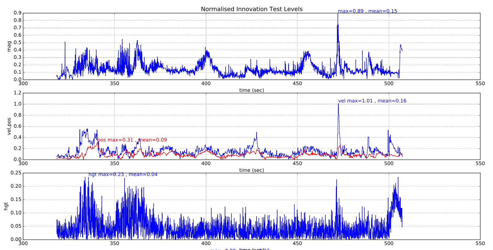
在正常操作期间,所有测试比率应保持在 0.5 以下,并且只有偶然的峰值高于此值,如下面成功飞行中的示例所示:
下图显示了具有良好隔离的多旋翼飞行器的 EKF 振动指标。 可以看到着陆冲击和起飞和着陆期间增加的振动。 如果收集的数据不足,使用这些指标无法提供有关最大阈值的具体建议。
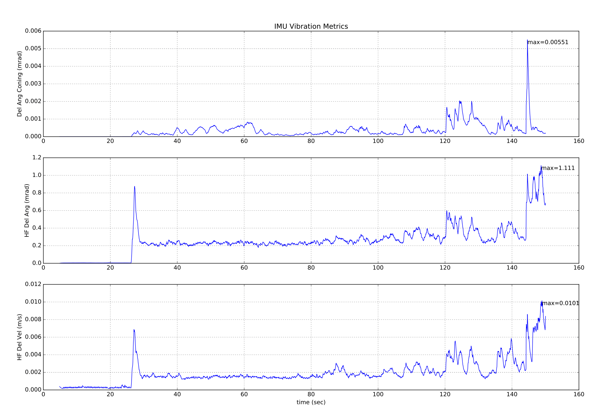
上述振动指标的数值有限值,因为在接近 IMU 采样频率的频率下存在的振动(大多数电路板为 1kHz)将导致在高频振动指标中未显示的数据中出现偏移。 检测混叠误差的唯一方法是它们对惯性导航精度和新息水平的提高。
除了生成 > 1.0 的大的位置和速度测试比率外,不同的误差机制还以不同的方式影响其它测试比率:
# 确定过度振动
高振动级别通常会影响垂直位置和速度新息以及水平分量。 磁力计测试级别仅受到很小程度的影响。
(在此插入示例绘图显示不好振动)
# 确定过度的陀螺偏差
大的陀螺偏差偏移通常的特征是在飞行期间增量角度偏差值的变化大于 5E-4(相当于 ~3 度/秒),并且如果偏航轴受到影响,也会导致磁强计测试比大幅增加。 除极端情况外,高度通常不受影响。 如果滤波器在飞行前给定时间稳定,则可以容忍接通最高 5 度/秒的偏差值。 如果位置发散,飞手进行的飞行前检查应防止解锁。
(在此插入示例图表显示不好的陀螺偏差)
# 确定较差的偏航精度
由于惯性导航和 GPS 测量计算出的速度方向不一致,因此不良偏航对准导致无人机开始移动时速度测试比率迅速增加。 磁强计的新息受到轻微影响。 高度通常不受影响。
(在此插入示例绘图显示不好的偏航对齐)
# 确定较差的GPS 数据精度
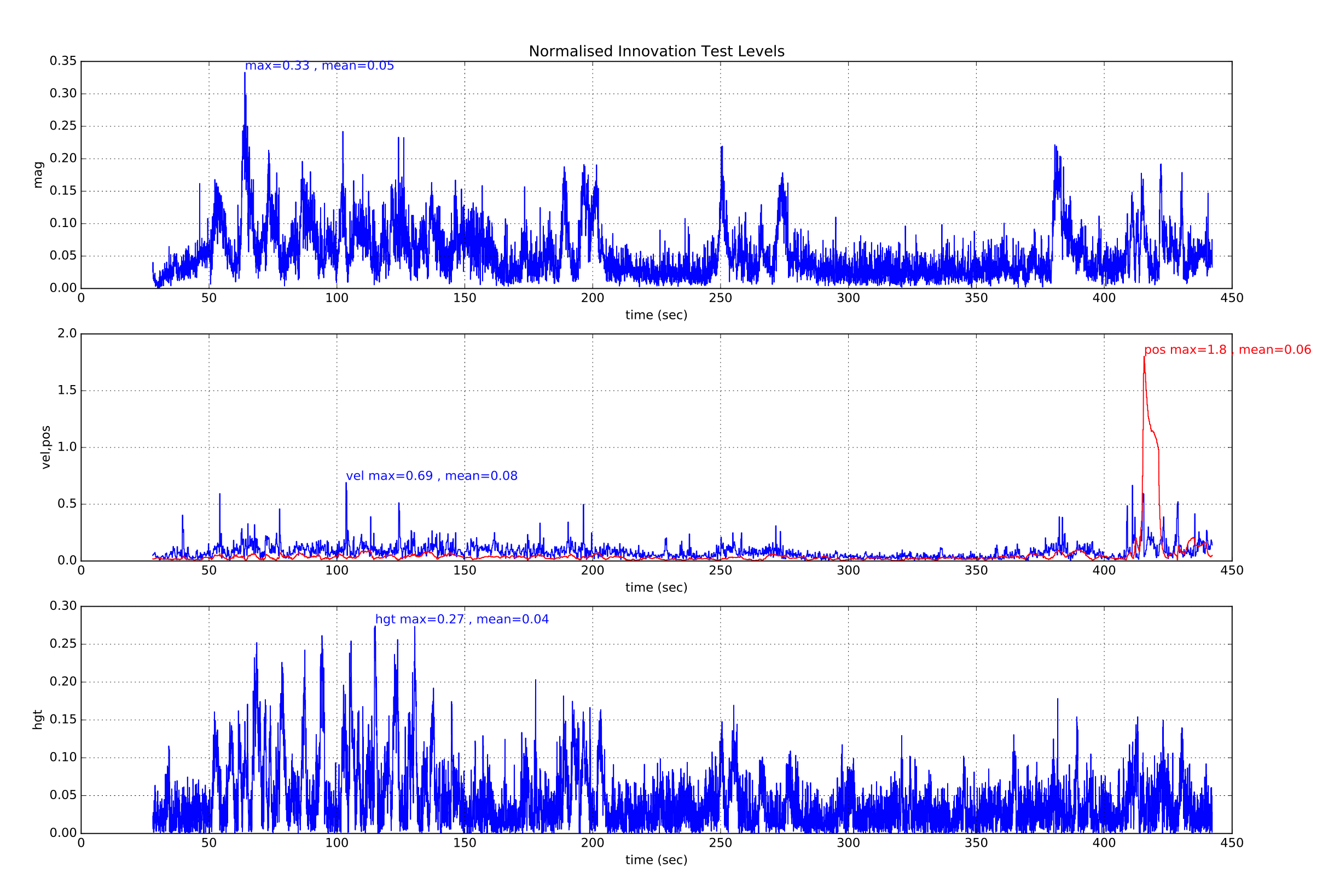
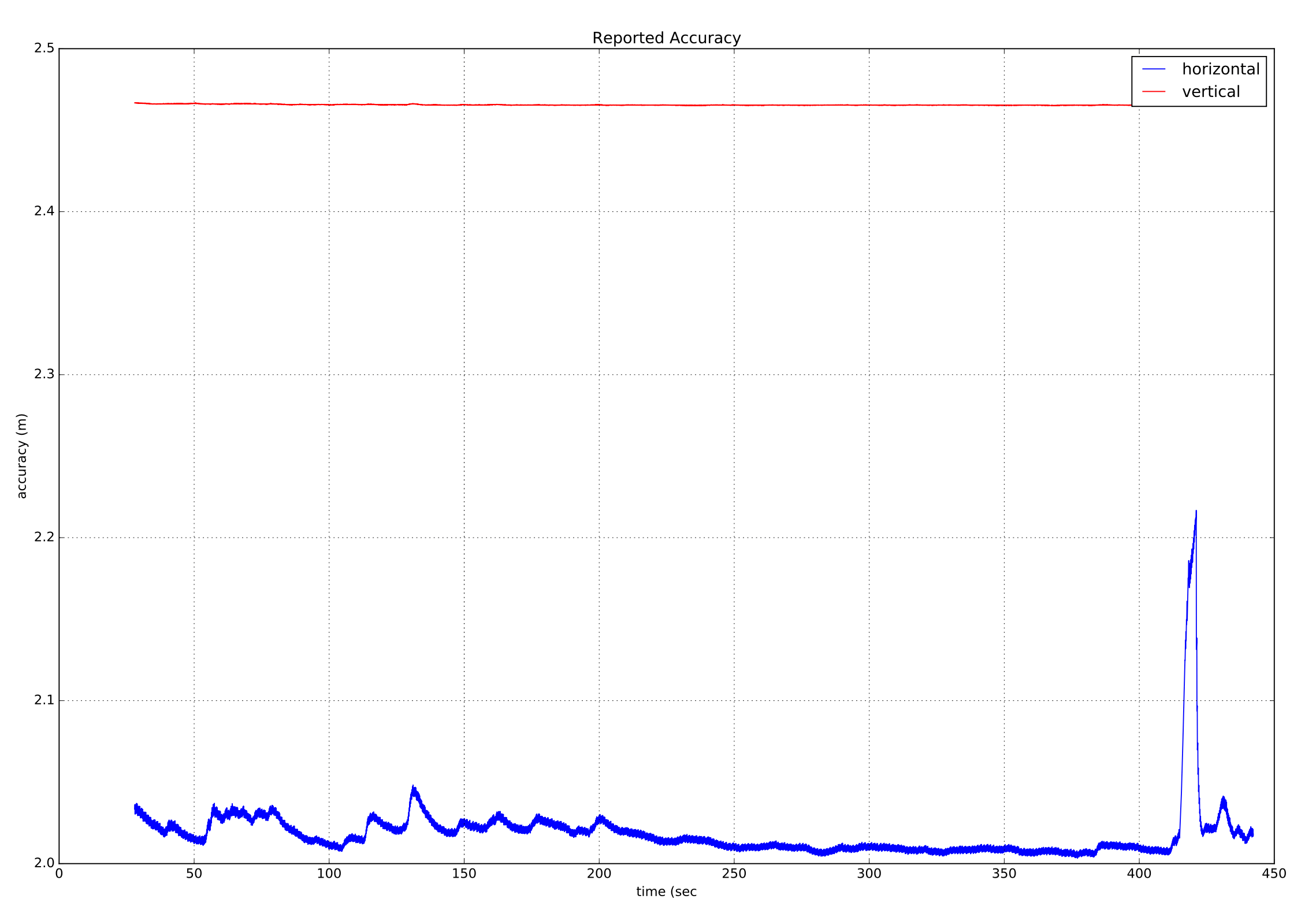
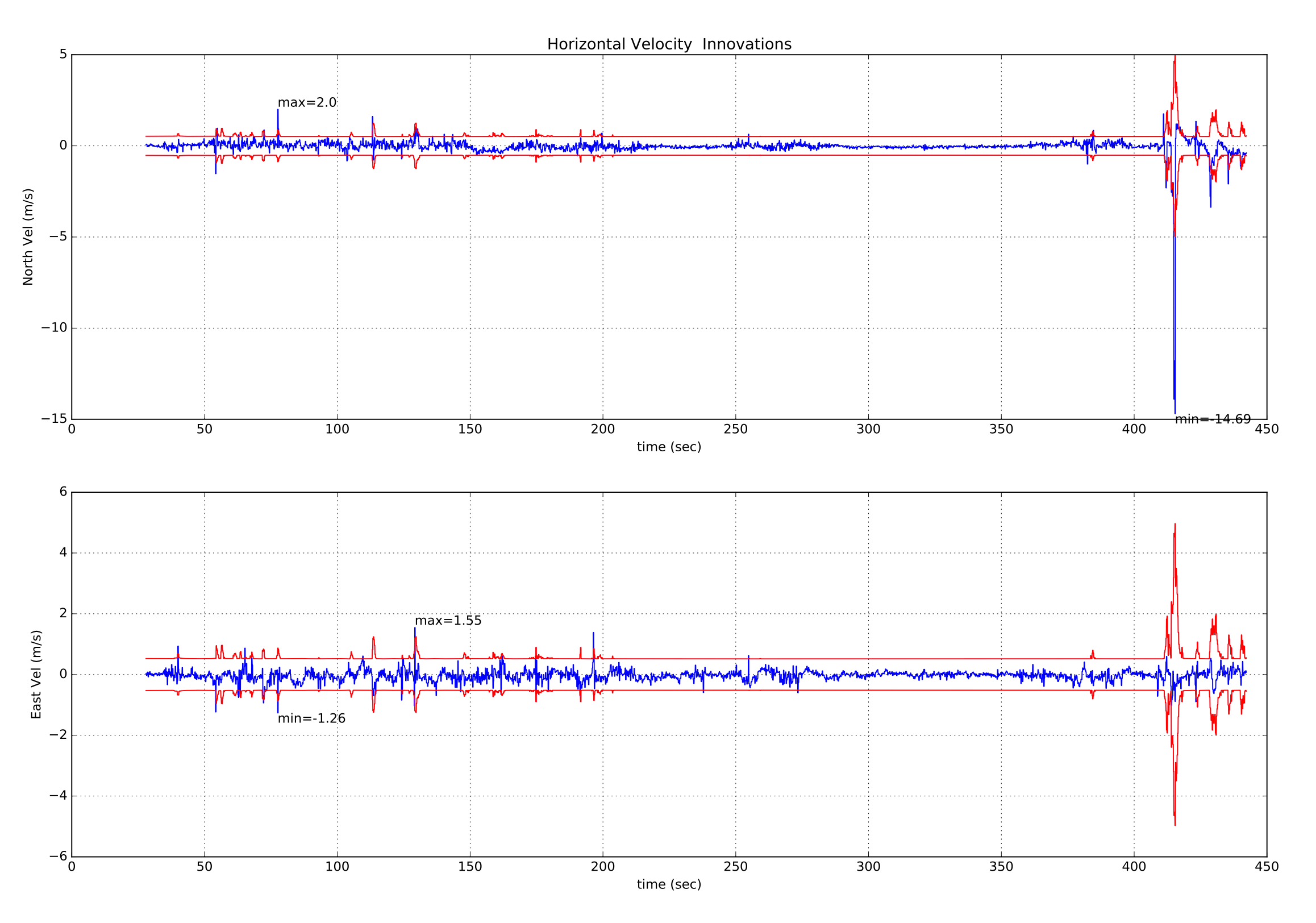
GPS 数据精度差通常伴随着接收器报告的速度误差的增加以及新息的增加。 由多路径,遮蔽和干扰引起的瞬态误差是更常见的原因。 下面是一个暂时失去 GPS 数据精度的例子,其中多旋翼飞行器开始从其游荡位置漂移并且必须使用摇杆进行校正。 The rise in EstimatorStatus (opens new window).vel_test_ratio to greater than 1 indicates the GPs velocity was inconsistent with other measurements and has been rejected.
这伴随着 GPS 接收器报告的速度精度的上升,这表明它可能是 GPS 误差。
如果我们还看一下 GPS 水平速度新息和新息差异,我们可以看到北向速度新息伴随着这次 GPS “故障”事件的大幅增长。
# 确定 GPS 数据的丢失
GPS 数据的丢失将通过速度和位置新息测试比率 'flat-lining' 来显示。 如果发生这种情况,请检查 vehicle_gps_position 中的其它 GPS 状态数据以获取更多信息。
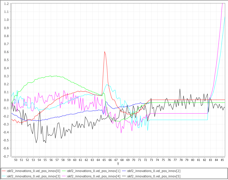
The following plot shows the NED GPS velocity innovations ekf2_innovations_0.vel_pos_innov[0 ... 2], the GPS NE position innovations ekf2_innovations_0.vel_pos_innov[3 ... 4] and the Baro vertical position innovation ekf2_innovations_0.vel_pos_innov[5] generated from a simulated VTOL flight using SITL Gazebo.
模拟的 GPS 在 73 秒时失锁。 注意 GPS 丢失后,NED 速度新息和 NE 位置新息 'flat-line' 。 注意在没有 GPS 数据的 10 秒后,EKF 使用最后的已知位置恢复到静态位置模式,并且 NE 位置新息开始再次改变。
# 气压计地面效应补偿
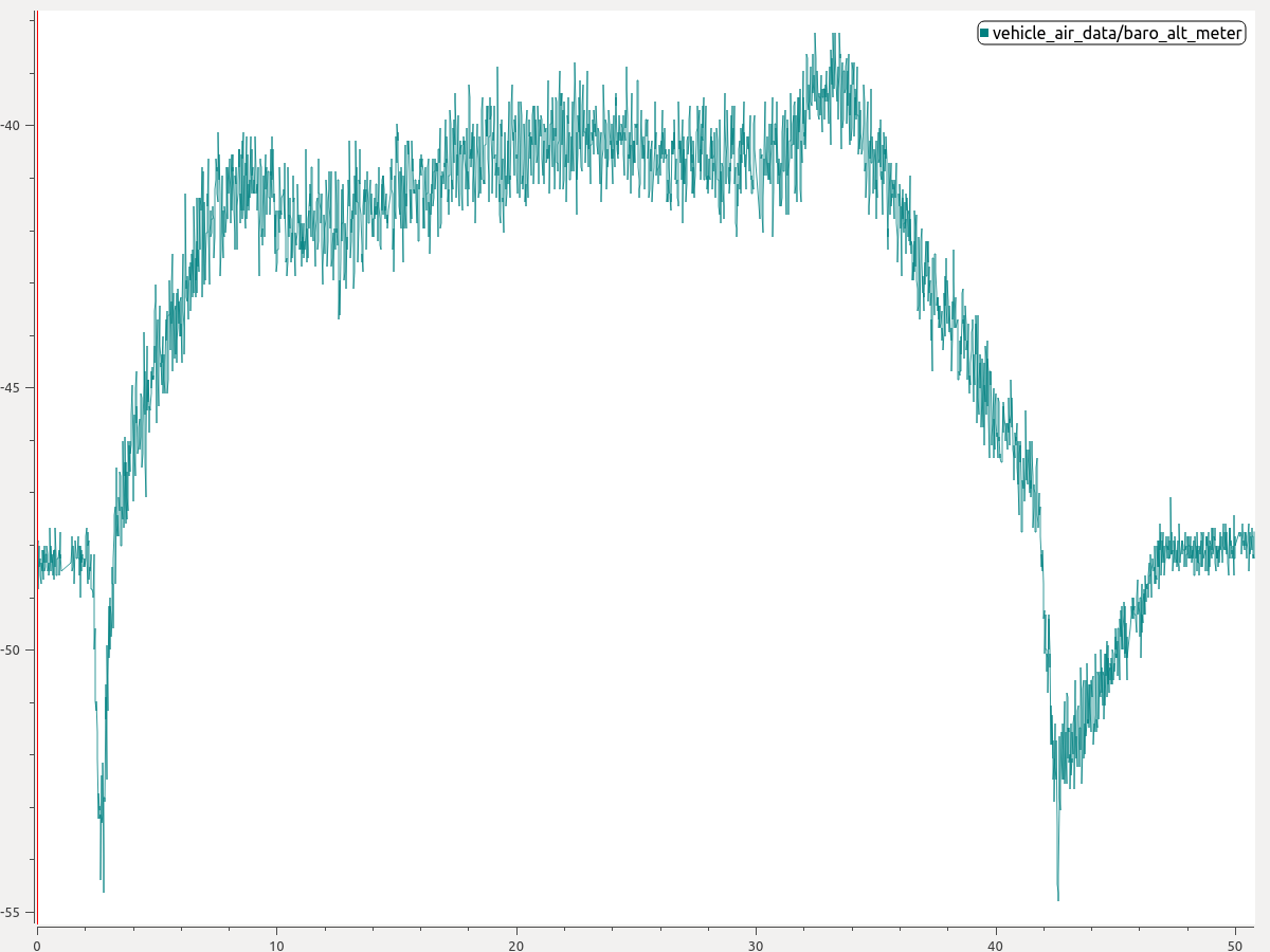
如果机体在降落期间在靠近地面时往往爬升回到空中, 最可能的原因是气压计地面效应。
这种情况是在推进器向地面推进并在无人机下空形成高压区时造成的。 其结果是降低了对压力高度的解读,从而导致了不必要的爬升。 下图显示了存在地面效应的典型情况。 注意气压计信号如何在飞行开始和结束时消失。
You can enable ground effect compensation to fix this problem:
- 从绘图中估算出气压计在起飞或着陆期间的跌落程度。 在上面的绘图中,人们可以看到降落过程中大约6米的气压计下沉。
- 然后将参数 EKF2_GND_EFF_DZ 设置为该值,并添加 10% 的余量值。 因此,在这种情况下,6.6米的数值将是一个良好的起点。
如果有可用的地形估计(例如,机体装备了测距仪),然后你可以另外指定EKF2_GND_MAX_HGT, 即距地高度,低于该高度,地面效应补偿将被激活。 如果没有可用的地形估计,这个参数将不会产生任何效果,系统将使用继承法来确定是否应激活地面效果补偿。
# 更多信息:
- PX4 State Estimation Overview (opens new window), PX4 Developer Summit 2019, Dr. Paul Riseborough): Overview of the estimator, and major changes from 2018/19, and the expected improvements through 2019/20.