Holybro Kakute F7 (Discontinued)
DiscontinuedWARNING
PX4 does not manufacture this (or any) autopilot. Contact the manufacturer for hardware support or compliance issues.
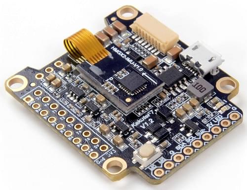
The Kakute F7 from Holybro is a flight controller board designed for racers.
INFO
This flight controller is manufacturer supported.
주요 특징
- Main System-on-Chip: STM32F745VGT6
- CPU : 단정밀도 FPU의 216MHz ARM Cortex M7
- RAM : 320KB SRAM
- FLASH: 1 MB
- 표준 레이서 폼 팩터 : 36x36mm, 표준 30.5mm 구멍 패턴
- ICM20689 가속/자이로 (소프트 장착)
- BMP280 기압계
- microSD (로깅)
- 6개의 UART
- I2C 버스 1 개
- 6 PWM 출력
- 내장 OSD 칩(SPI를 통한 AB7456)
구매처
The board can be bought from one of the following shops (for example):
TIP
The Kakute F7 is designed to work with the Tekko32 4-in-1 ESC and they can be bought in combination.
커넥터 및 핀
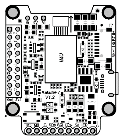
This is the silkscreen for the Kakute F7, showing the top of the board:
| 핀 | 기능 | 기본값 |
|---|---|---|
| B+ | 배터리 양극 전압 (2S-6S) | |
| 5V | 5V 출력 (최대 2A) | |
| VO | 비디오 송신기로 비디오 출력 | |
| VI | FPV 카메라의 비디오 입력 | |
| G 또는 GND | 접지 | |
| SDA, SCL | I2C 연결(주변장치용) | |
| R1, T1 | UART1 RX 및 TX | TELEM1 |
| R2, T2 | UART2 RX 및 TX | TELEM2 |
| R3, T3 | UART3 RX 및 TX | NuttX 디버그 콘솔 |
| R4, T4 | UART4 RX 및 TX | GPS1 |
| R6, T6 | UART6 RX 및 TX | RC 포트 |
| R7, T7 | UART7 RX 및 TX(RX는 4-in-1 ESC와 함께 사용하기 위해 플러그에 있음) | DShot 텔레메트리 |
| LED | WS2182 주소 지정이 가능한 LED 신호 와이어(테스트되지 않음) | |
| Buz- | 피에조 부저 네거티브 레그(부저 포지티브 레그를 5V 패드에 연결) | |
| 3V3 | 3.3V 출력(최대 200mA) | |
| M1에서 M4 | 모터 신호 출력 (4-in-1 ESC에서 사용하기 위해 플러그에 위치) | |
| M5, M6 | 추가 모터 신호 출력(보드 측면에 위치) | |
| RSI | 수신기에서 아날로그 RSSI(0-3.3V) 입력 | |
| Boot | 부트로더 버튼 |
부트로더 업데이트
The board comes pre-installed with Betaflight. Before PX4 firmware can be installed, the PX4 bootloader must be flashed. Download the kakutef7_bl.hex bootloader binary and read this page for flashing instructions.
펌웨어 빌드
To build PX4 for this target:
make holybro_kakutef7_default펌웨어 설치
펌웨어는 일반적인 방법으로 설치할 수 있습니다.
- 소스 빌드 및 업로드
make holybro_kakutef7_default upload - Load the firmware using QGroundControl. 미리 빌드된 펌웨어나 사용자 지정 펌웨어를 사용할 수 있습니다.
설정
If you use a 4-in-1 ESC with Betaflight/Cleanflight motor assignment you can use the Actuator configuration UI to set the motor ordering appropriately.
In addition to the basic configuration, the following parameters are important:
| 매개변수 | 설정 |
|---|---|
| SYS_HAS_MAG | 보드에 내부 자력계가 없기 때문에 비활성화하여야 합니다. 외부 자력계를 연결하여 활성화 할 수 있습니다. |
시리얼 포트 매핑
| UART | 장치 | 포트 |
|---|---|---|
| USART1 | /dev/ttyS0 | TELEM1 |
| USART2 | /dev/ttyS1 | TELEM2 |
| USART3 | /dev/ttyS2 | 디버그 콘솔 |
| UART4 | /dev/ttyS3 | GPS1 |
| USART6 | /dev/ttyS4 | RC SBUS |
| UART7 | /dev/ttyS5 | ESC 텔레메트리(DShot) |
디버그 포트
시스템 콘솔
UART3 RX and TX are configured for use as the System Console.
SWD
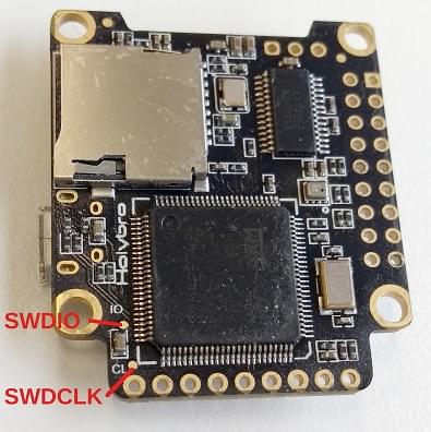
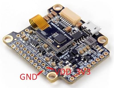
The SWD interface (JTAG) pins are:
SWCLK: Test Point 2 (Pin 72 on the CPU)SWDIO: Test Point 3 (Pin 76 on CPU)GND: As marked on boardVDD_3V3: As marked on board
These are shown below.