# Pixhawk Wiring Quick Start
WARNING
PX4 does not manufacture this (or any) autopilot. Contact the manufacturer (opens new window) for hardware support or compliance issues.
This quick start guide shows how to power the 3DR Pixhawk flight controller and connect its most important peripherals.
![]()
Note
The 3DR Pixhawk is no longer available from 3DR. Other flight controllers based on the Pixhawk FMUv2 architecture are available from other companies (these share the same connections, outputs, functions, etc. and are wired in a similar way).
# Wiring Chart Overview
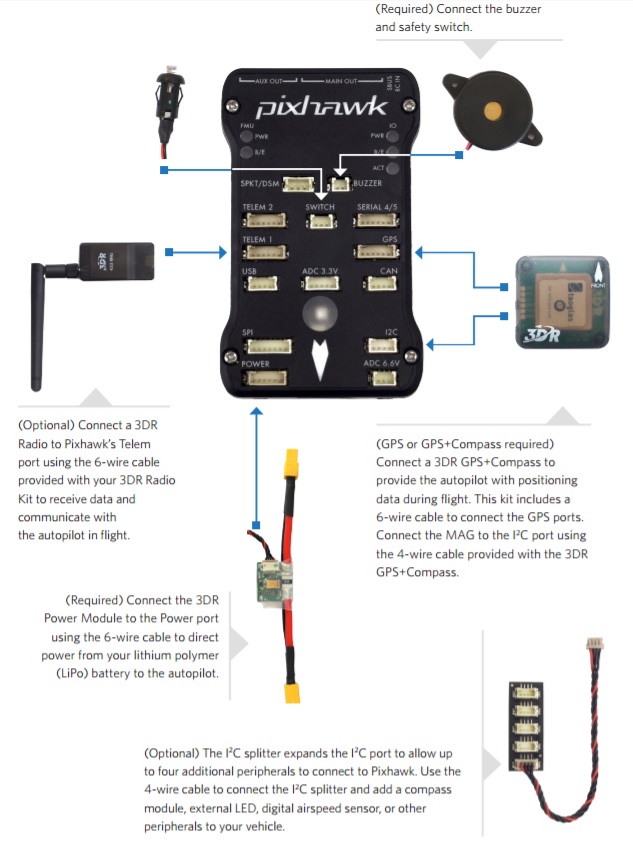
The image below shows standard Pixhawk connections (excepting the motor and servo outputs). We'll go through each main part in the following sections.
Note
More detailed wiring information is shown below.
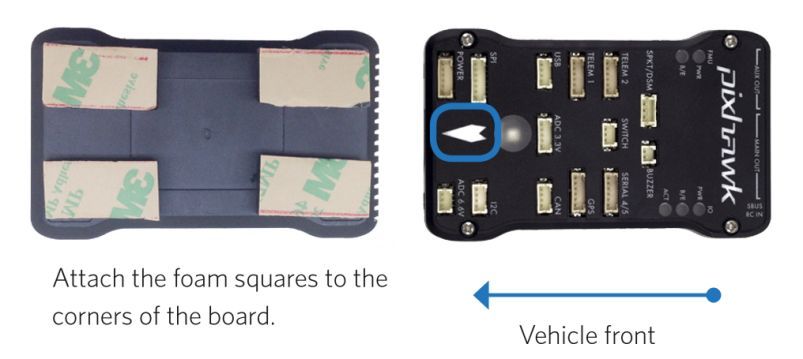
# Mount and Orient Controller
The Pixhawk should be mounted on the frame using vibration-damping foam pads (included in the kit). It should be positioned as close to your vehicle’s center of gravity as possible, oriented top-side up with the arrow points towards the front of the vehicle.
Note
If the controller cannot be mounted in the recommended/default orientation (e.g. due to space constraints) you will need to configure the autopilot software with the orientation that you actually used: Flight Controller Orientation.
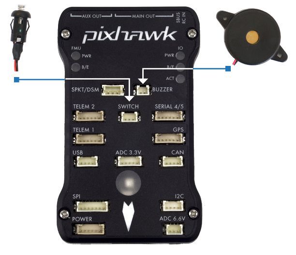
# Buzzer and Safety Switch
Connect the included buzzer and safety switch as shown below (these are mandatory).
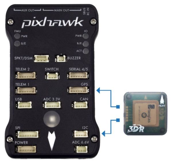
# GPS + Compass
Attach a GPS (required) to the GPS port using the 6-wire cable supplied in the kit. Optionally attach a compass to the I2C port using a 4-wire cable (the Pixhawk has an internal compass, which can be used if necessary).
Note
The diagram shows a combined GPS and Compass. The GPS/Compass should be mounted on the frame as far away from other electronics as possible, with the direction marker towards the front of the vehicle (separating the compass from other electronics will reduce interference).
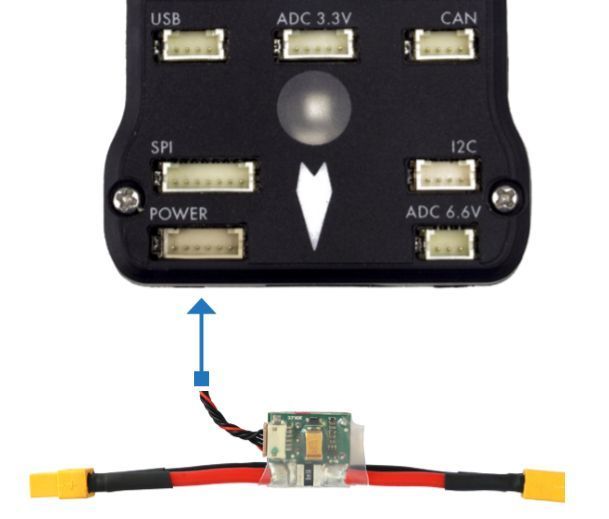
# Power
Connect the output of a Power module (PM) to the POWER port using a 6-wire cable as shown. The PM input will be connected to your LiPo battery, while the main output will supply vehicle ESCs/motors (possibly via a power distribution board).
The power module supplies the flight controller with power from the battery and also sends information about the analog current and voltage supplied via the module (including both power to the flight controller and to motors etc).
WARNING
The power module supplies the flight controller itself, but cannot power servos and other hardware connected to the controller's output ports (rail). For copter this does not matter because the motors are separately powered.
For planes and VTOL the output rail will need to be separately powered in order to drive servos for rudders, elevons etc. Often the main pusher/puller motor uses an ESC with an integrated BEC (opens new window) that can be connected to the Pixhawk output rail. If not, you will need to setup a 5V BEC to connect to one of the free Pixhawk ports (without power, the servos will not work).
# Radio Control
A remote control (RC) radio system is required if you want to manually control your vehicle (PX4 does not require a radio system for autonomous flight modes).
You will need to select a compatible transmitter/receiver and then bind them so that they communicate (read the instructions that come with your specific transmitter/receiver).
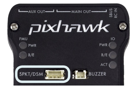
The instructions below show how to connect the different types of receivers to Pixhawk:
Spektrum and DSM receivers connect to the SPKT/DSM input.
PPM-SUM and S.BUS receivers connect to the RC ground, power and signal pins as shown.
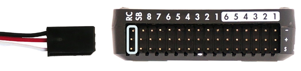
PPM and PWM receivers that have an individual wire for each channel must connect to the RC port via a PPM encoder like this one (opens new window) (PPM-Sum receivers use a single signal wire for all channels).
For more information about selecting a radio system, receiver compatibility, and binding your transmitter/receiver pair, see: Remote Control Transmitters & Receivers.
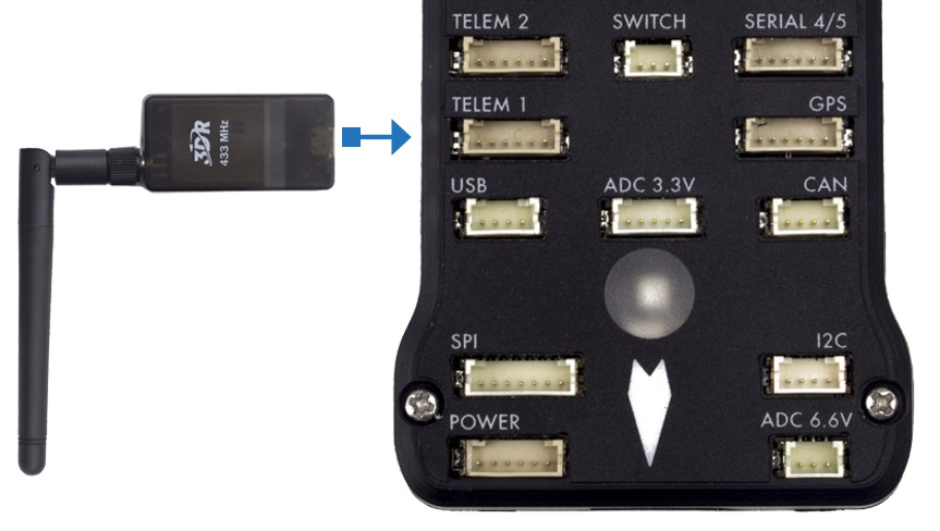
# Telemetry Radios (Optional)
Telemetry radios may be used to communicate and control a vehicle in flight from a ground station (for example, you can direct the UAV to a particular position, or upload a new mission). One radio must be connected to your vehicle as shown below. The other is connected to your ground station computer or mobile device (usually by USB).
# Motors
The mappings between MAIN/AUX output ports and motor/servos for all supported air and ground frames are listed in the Airframe Reference.
:::caution The mapping is not consistent across frames (e.g. you can't rely on the throttle being on the same output for all plane frames). Make sure to use the correct mapping for your vehicle. :::
TIP
If your frame is not listed in the reference then use a "generic" airframe of the correct type.
Note
The output rail must be separately powered, as discussed in the Power section above.
# Other Peripherals
The wiring and configuration of other components is covered within the topics for individual peripherals.
# Configuration
General configuration information is covered in: Autopilot Configuration.
QuadPlane specific configuration is covered here: QuadPlane VTOL Configuration
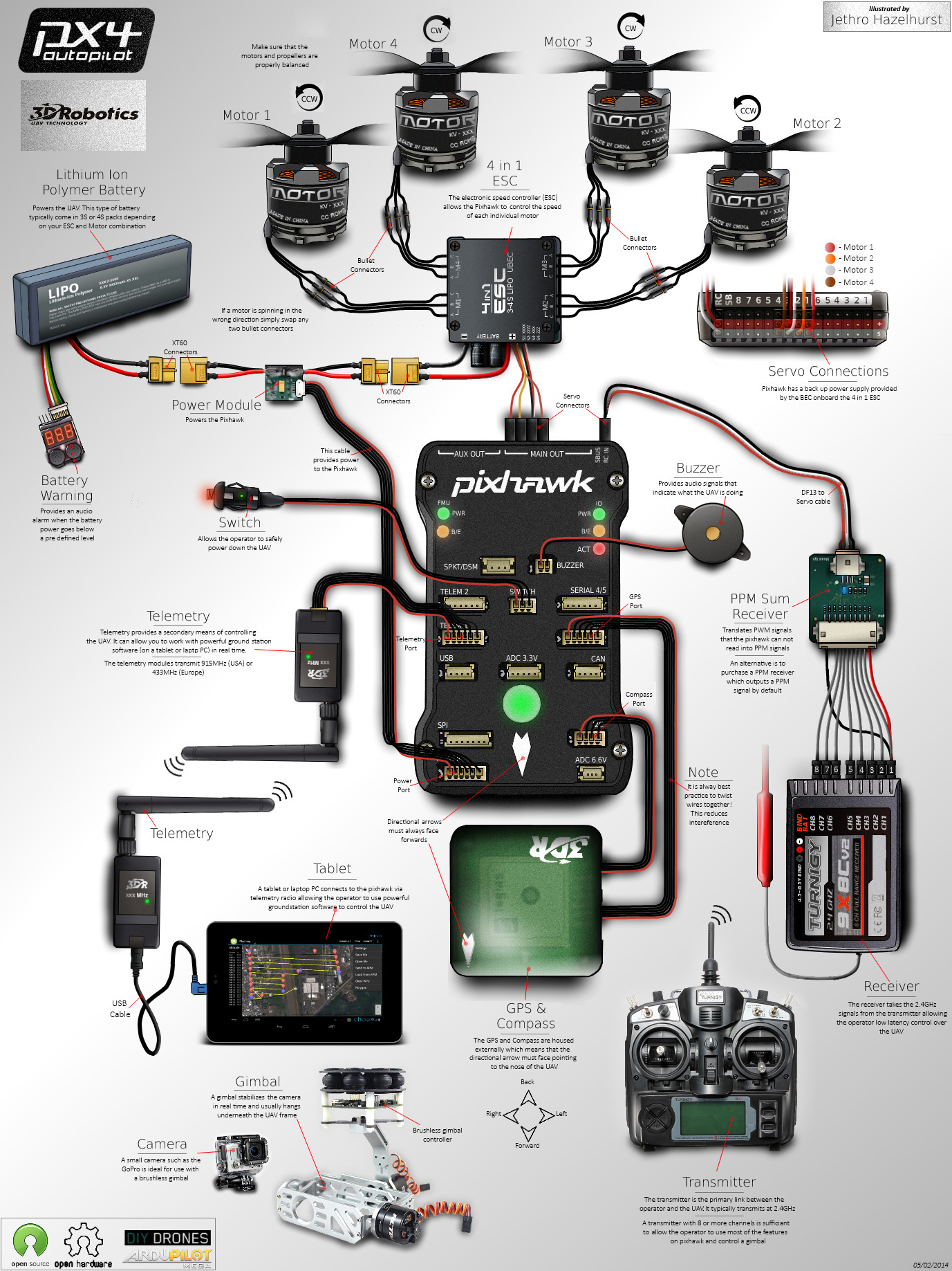
# Detailed Wiring Infographic (Copter)