# 3DR Pixhawk 1 Flight Controller (Discontinued)
WARNING
PX4 does not manufacture this (or any) autopilot. Contact the manufacturer for support or compliance issues.
WARNING
This flight controller has been discontinued and is no longer commercially available. You can use the mRo Pixhawk as a drop-in replacement.
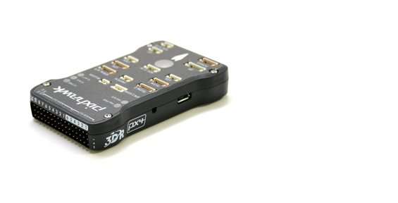
The 3DR Pixhawk® 1 autopilot is a popular general purpose flight controller based on the Pixhawk-project (opens new window) FMUv2 open hardware design (it combines the functionality of the PX4FMU + PX4IO). It runs PX4 on the NuttX (opens new window) OS.
Assembly/setup instructions for use with PX4 are provided here: Pixhawk Wiring Quickstart
# Key Features
- Main System-on-Chip: STM32F427 (opens new window)
- CPU: 180 MHz ARM® Cortex® M4 with single-precision FPU
- RAM: 256 KB SRAM (L1)
- Failsafe System-on-Chip: STM32F100
- CPU: 24 MHz ARM Cortex M3
- RAM: 8 KB SRAM
- Wifi: ESP8266 external
- GPS: u-blox® 7/8 (Hobbyking®) / u-blox 6 (3D Robotics)
- Optical flow: PX4 Flow unit
- Redundant power supply inputs and automatic failover
- External safety switch
- Multicolor LED main visual indicator
- High-power, multi-tone piezo audio indicator
- microSD card for high-rate logging over extended periods of time
Connectivity
- 1x I2C
- 1x CAN (2x optional)
- 1x ADC
- 4x UART (2x with flow control)
- 1x Console
- 8x PWM with manual override
- 6x PWM / GPIO / PWM input
- S.BUS / PPM / Spektrum input
- S.BUS output
# Where to Buy
Originally manufactured by 3DR® this board was the original standard microcontroller platform for PX4®. While the board is no longer manufactured by 3DR, you can use the mRo Pixhawk as a drop-in replacement.
Order mRo Pixhawk from:
- Bare Bones (opens new window) - Just the board (useful as a 3DR Pixhawk replacement)
- mRo Pixhawk 2.4.6 Essential Kit (opens new window) - includes everything except for telemetry radios
- mRo Pixhawk 2.4.6 Cool Kit! (Limited edition) (opens new window) - includes everything you need including telemetry radios
# Specifications
# Processor
- 32bit STM32F427 Cortex-M4F (opens new window) core with FPU
- 168 MHz
- 256 KB RAM
- 2 MB Flash
- 32 bit STM32F103 failsafe co-processor
# Sensors
- ST Micro L3GD20H 16 bit gyroscope
- ST Micro LSM303D 14 bit accelerometer / magnetometer
- Invensense MPU 6000 3-axis accelerometer/gyroscope
- MEAS MS5611 barometer
# Interfaces
- 5x UART (serial ports), one high-power capable, 2x with HW flow control
- 2x CAN (one with internal 3.3V transceiver, one on expansion connector)
- Spektrum DSM / DSM2 / DSM-X® Satellite compatible input
- Futaba S.BUS® compatible input and output
- PPM sum signal input
- RSSI (PWM or voltage) input
- I2C
- SPI
- 3.3 and 6.6V ADC inputs
- Internal microUSB port and external microUSB port extension
# Power System and Protection
- Ideal diode controller with automatic failover
- Servo rail high-power (max. 10V) and high-current (10A+) ready
- All peripheral outputs over-current protected, all inputs ESD protected
# Voltage Ratings
Pixhawk can be triple-redundant on the power supply if three power sources are supplied. The three rails are: Power module input, servo rail input, USB input.
# Normal Operation Maximum Ratings
Under these conditions all power sources will be used in this order to power the system
- Power module input (4.8V to 5.4V)
- Servo rail input (4.8V to 5.4V) UP TO 10V FOR MANUAL OVERRIDE, BUT AUTOPILOT PART WILL BE UNPOWERED ABOVE 5.7V IF POWER MODULE INPUT IS NOT PRESENT
- USB power input (4.8V to 5.4V)
# Absolute Maximum Ratings
Under these conditions the system will not draw any power (will not be operational), but will remain intact.
- Power module input (4.1V to 5.7V, 0V to 20V undamaged)
- Servo rail input (4.1V to 5.7V, 0V to 20V)
- USB power input (4.1V to 5.7V, 0V to 6V)
# Schematics
FMUv2 + IOv2 schematic (opens new window) -- Schematic and layout
Note
As a CC-BY-SA 3.0 licensed Open Hardware design, all schematics and design files are available (opens new window).
# Connectors
TIP
The RC IN port is for RC receivers only and provides power. NEVER connect any servos, power supplies or batteries to it or to the receiver connected to it.
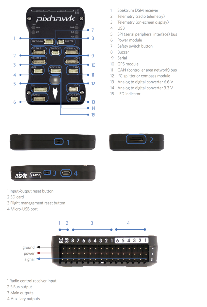
# Pinouts
# TELEM1, TELEM2 ports
| Pin | Signal | Volt |
|---|---|---|
| 1 (red) | VCC | +5V |
| 2 (blk) | TX (OUT) | +3.3V |
| 3 (blk) | RX (IN) | +3.3V |
| 4 (blk) | CTS (IN) | +3.3V |
| 5 (blk) | RTS (OUT) | +3.3V |
| 6 (blk) | GND | GND |
# GPS port
| Pin | Signal | Volt |
|---|---|---|
| 1 (red) | VCC | +5V |
| 2 (blk) | TX (OUT) | +3.3V |
| 3 (blk) | RX (IN) | +3.3V |
| 4 (blk) | CAN2 TX | +3.3V |
| 5 (blk) | CAN2 RX | +3.3V |
| 6 (blk) | GND | GND |
# SERIAL 4/5 port
Due to space constraints two ports are on one connector.
| Pin | Signal | Volt |
|---|---|---|
| 1 (red) | VCC | +5V |
| 2 (blk) | TX (#4) | +3.3V |
| 3 (blk) | RX (#4) | +3.3V |
| 4 (blk) | TX (#5) | +3.3V |
| 5 (blk) | RX (#5) | +3.3V |
| 6 (blk) | GND | GND |
# ADC 6.6V
| Pin | Signal | Volt |
|---|---|---|
| 1 (red) | VCC | +5V |
| 2 (blk) | ADC IN | up to +6.6V |
| 3 (blk) | GND | GND |
# ADC 3.3V
| Pin | Signal | Volt |
|---|---|---|
| 1 (red) | VCC | +5V |
| 2 (blk) | ADC IN | up to +3.3V |
| 3 (blk) | GND | GND |
| 4 (blk) | ADC IN | up to +3.3V |
| 5 (blk) | GND | GND |
# I2C
| Pin | Signal | Volt |
|---|---|---|
| 1 (red) | VCC | +5V |
| 2 (blk) | SCL | +3.3 (pullups) |
| 3 (blk) | SDA | +3.3 (pullups) |
| 4 (blk) | GND | GND |
# CAN
| Pin | Signal | Volt |
|---|---|---|
| 1 (red) | VCC | +5V |
| 2 (blk) | CAN_H | +12V |
| 3 (blk) | CAN_L | +12V |
| 4 (blk) | GND | GND |
# SPI
| Pin | Signal | Volt |
|---|---|---|
| 1 (red) | VCC | +5V |
| 2 (blk) | SPI_EXT_SCK | +3.3 |
| 3 (blk) | SPI_EXT_MISO | +3.3 |
| 4 (blk) | SPI_EXT_MOSI | +3.3 |
| 5 (blk) | !SPI_EXT_NSS | +3.3 |
| 6 (blk) | !GPIO_EXT | +3.3 |
| 7 (blk) | GND | GND |
# POWER
| Pin | Signal | Volt |
|---|---|---|
| 1 (red) | VCC | +5V |
| 2 (blk) | VCC | +5V |
| 3 (blk) | CURRENT | +3.3V |
| 4 (blk) | VOLTAGE | +3.3V |
| 5 (blk) | GND | GND |
| 6 (blk) | GND | GND |
# SWITCH
| Pin | Signal | Volt |
|---|---|---|
| 1 (red) | VCC | +3.3V |
| 2 (blk) | !IO_LED_SAFETY | GND |
| 3 (blk) | SAFETY | GND |
# Serial Port Mapping
| UART | Device | Port |
|---|---|---|
| UART1 | /dev/ttyS0 | IO debug |
| USART2 | /dev/ttyS1 | TELEM1 (flow control) |
| USART3 | /dev/ttyS2 | TELEM2 (flow control) |
| UART4 | ||
| UART7 | CONSOLE | |
| UART8 | SERIAL4 |
# Debug Ports
# Console Port
The PX4 System Console runs on the port labeled SERIAL4/5.
TIP
A convenient way to connect to the console is to use a Dronecode probe (opens new window), as it comes with connectors that can be used with several different Pixhawk devices.
Simply connect the 6-pos DF13 1:1 cable on the Dronecode probe (opens new window) to the Pixhawk SERIAL4/5 port.
The pinout is standard serial pinout, designed to connect to a 3.3V FTDI (opens new window) cable (5V tolerant).
| 3DR Pixhawk 1 | FTDI | |
|---|---|---|
| 1 | +5V (red) | |
| 2 | S4 Tx | |
| 3 | S4 Rx | |
| 4 | S5 Tx | 5 |
| 5 | S5 Rx | 4 |
| 6 | GND | 1 |
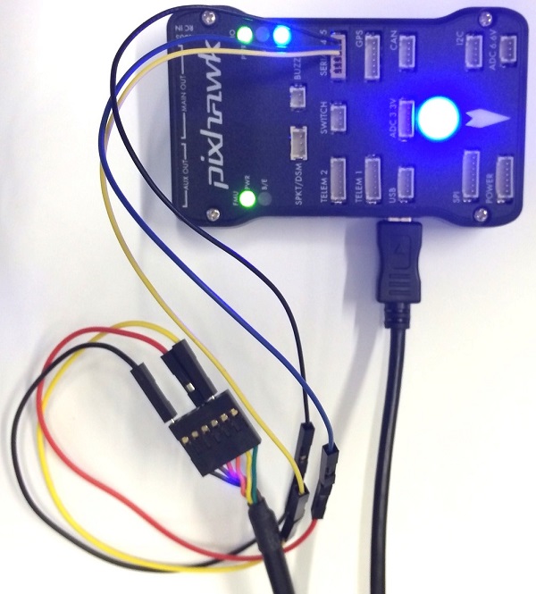
The wiring for an FTDI cable to a 6-pos DF13 1:1 connector is shown in the figure below.
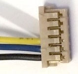
The complete wiring is shown below.
Note
For information on how to use the console see: System Console.
# SWD Port
The SWD (JTAG) ports are hidden under the cover (which must be removed for hardware debugging). There are separate ports for FMU and IO, as highlighted below.
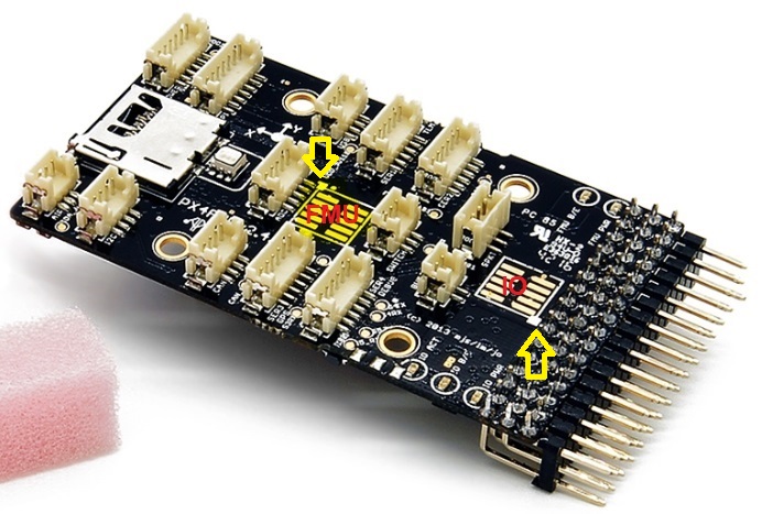
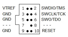
The ports are ARM 10-pin JTAG connectors, which you will probably have to solder. The pinout for the ports is shown below (the square markers in the corners above indicates pin 1).
Note
All Pixhawk FMUv2 boards have a similar SWD port.
# Building Firmware
TIP
Most users will not need to build this firmware! It is pre-built and automatically installed by QGroundControl when appropriate hardware is connected.
To build PX4 for this target:
make px4_fmu-v2_default
# Parts / Housings
- ARM MINI JTAG (J6): 1.27 mm 10pos header (SHROUDED), for Black Magic Probe: FCI 20021521-00010D4LF (Distrelec (opens new window), Digi-Key (opens new window),) or Samtec FTSH-105-01-F-DV-K (untested) or Harwin M50-3600542 (Digikey (opens new window) or Mouser (opens new window))
- JTAG Adapter Option #1: BlackMagic Probe (opens new window). Note, may come without cables (check with manufacturer). If so, you will need the Samtec FFSD-05-D-06.00-01-N cable (Samtec sample service (opens new window) or Digi-Key Link: SAM8218-ND (opens new window)) or Tag Connect Ribbon (opens new window) and a Mini-USB cable.
- JTAG Adapter Option #2: Digi-Key Link: ST-LINK/V2 (opens new window) / ST USER MANUAL (opens new window), needs an ARM Mini JTAG to 20pos adapter: Digi-Key Link: 726-1193-ND (opens new window)
- JTAG Adapter Option #3: SparkFun Link: Olimex ARM-TINY (opens new window) or any other OpenOCD-compatible ARM Cortex JTAG adapter, needs an ARM Mini JTAG to 20pos adapter: Digi-Key Link: 726-1193-ND (opens new window)
- USARTs: Hirose DF13 6 pos (Digi-Key Link: DF13A-6P-1.25H(20) (opens new window))
- Mates: Hirose DF13 6 pos housing (Digi-Key Link: Hirose DF13-6S-1.25C (opens new window))
- I2C and CAN: Hirose DF13 4 pos (Digi-Key Link: DF13A-4P-1.25H(20) (opens new window))
# Supported Platforms / Airframes
Any multicopter / airplane / rover or boat that can be controlled with normal RC servos or Futaba S-Bus servos.