# I2C Bus Peripherals
I2C (opens new window) is a serial communication protocol that is commonly used (at least on smaller drones), for connecting peripheral components like rangefinders, LEDs, Compass, etc.
It is recommended for:
- Connecting offboard components that require low bandwidth and low latency communication, e.g. rangefinders, magnetometers, airspeed sensors and tachometers .
- Compatibility with peripheral devices that only support I2C.
- Allowing multiple devices to attach to a single bus, which is useful for conserving ports.
I2C allows multiple master devices to connect to multiple slave devices using only 2 wires per connection (SDA, SCL). in theory a bus can support 128 devices, each accessed via its unique address.
Note
UAVCAN would normally be preferred where higher data rates are required, and on larger vehicles where sensors are be mounted further from the flight controller.
# Wiring
I2C uses a pair of wires: SDA (serial data) and SCL (serial clock).
The bus is of open-drain type, meaning that devices ground the data line.
It uses a pullup resistor to push it to log.1 (idle state) - every wire has it usually located on the bus terminating devices.
One bus can connect to multiple I2C devices.
The individual devices are connected without any crossing.
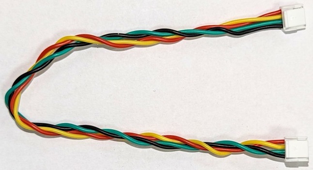
For connection (according to dronecode standard) 4-wire cables equipped with JST-GH connectors are used. To ensure reliable communication and to reduce crosstalk it is advised to apply recommendations concerning cable twisting and pullup resistors placement.
# Checking the Bus and Device Status
A useful tool for bus analysis is i2cdetect. This lists available I2C devices by their addresses. It can be used to find out if a device on the bus is available and if the autopilot can communicate with it.
The tool can be run in the PX4 terminal with the following command:
i2cdetect -b 1
where the bus number is specified after -b parameter
# Common problems
# Address Clashes
If two I2C devices on a bus have the same ID there will be a clash, and neither device will not work properly (or at all). This usually occurs because a user needs to attach two sensors of the same type to the bus, but may also happen if devices use duplicate addresses by default.
Particular I2C devices may allow you to select a new address for one of the devices to avoid the clash. Some devices do not support this option, or do not have broad options for the addresses that can be used (i.e. cannot be used to avoid a clash).
If you can't change the addresses, one option is to use an I2C Address Translator.
# Insufficient Transfer Capacity
The bandwidth available for each individual device generally decreases as more devices are added. The exact decrease depends on the bandwidth used by each individual device. Therefore it is possible to connect many low bandwidth devices, like tachometers. If too many devices are added, it can cause transmission errors and network unreliability.
There are several ways to reduce the problem:
- Dividing the devices into groups, each with approximately the same number of devices and connecting each group to one autopilot port
- Increase bus speed limit (usually set to 100kHz for external I2C bus)
# Excessive Wiring Capacitance
The electrical capacity of bus wiring increases as more devices/wires are added. The exact decrease depends on total length of bus wiring and wiring specific capacitance. The problem can be analyzed using an oscilloscope, where we see that the edges of SDA/SCL signals are no longer sharp.
There are several ways to reduce the problem:
- Dividing the devices into groups, each with approximately the same number of devices and connecting each group to one autopilot port
- Using the shortest and the highest quality I2C cables possible
- Separating the devices with a weak open-drain driver to smaller bus with lower capacitance
- I2C Bus Accelerators
# I2C Bus Accelerators
I2C bus accelerators are separate circuits that can be used to support longer wiring length on an I2C bus. They work by physically dividing an I2C network into 2 parts and using their own transistors to amplify I2C signals.
Available accelerators include:
- Thunderfly TFI2CEXT01 (opens new window):
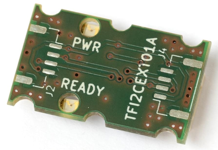
- This has Dronecode connectors and is hence very easy to add to a Pixhawk I2C setup.
- The module has no settings (it works out of the box).
# I2C Address Translators
I2C Address Translators can be used to prevent I2C address clashes in systems where there is no other way to assign unique addresses. The work by listening for I2C communication and transforming the address when a slave device is called (according to a preset algorithm).
Supported I2C Address Translators include:
# I2C Development
Software development for I2C devices is described in I2C Bus (Development Overview).
# Further Information
- I2C (opens new window) (Wikipedia)
- I2C Comparative Overview (opens new window) (learn.sparkfun.com)
- Driver Framework