# Connecting an RC Receiver on Linux (Including S.Bus)
This topic shows how to setup a PX4 Linux-based autopilot to connect and use a supported RC receiver on any serial port.
For RC types other than S.Bus, you can just connect the receiver directly to the serial ports, or to USB via a USB to TTY serial cable (e.g. like PL2302 USB to Serial TTL converter).
Note
For an S.Bus receiver (or encoder - e.g. from Futaba, RadioLink, etc.) you will usually need to connect the receiver and device via a signal inverter circuit, but otherwise the setup is the same.
Then Start the PX4 RC Driver on the device, as shown below.
# Starting the Driver
To start the RC driver on a particular UART (e.g. in this case /dev/ttyS2):
rc_input start -d /dev/ttyS2
For other driver usage information see: rc_input.
# Signal Inverter Circuit (S.Bus only)
S.Bus is an inverted UART communication signal.
While some serial ports/flight controllers can read an inverted UART signal, most require a signal inverter circuit between the receiver and serial port to un-invert the signal.
TIP
This circuit is also required to read S.Bus remote control signals through the serial port or USB-to-TTY serial converter.
This section shows how to create an appropriate circuit.
# Required Components
- 1x NPN transistor (e.g. NPN S9014 TO92)
- 1x 10K resistor
- 1x 1K resistor
Note
Any type/model of transistor can be used because the current drain is very low.
# Circuit Diagram/Connections
Connect the components as described below (and shown in the circuit diagram):
- S.Bus signal → 1K resistor → NPN transistor base
- NPN transistor emit → GND
- 3.3VCC → 10K resistor → NPN transistor collection → USB-to-TTY rxd
- 5.0VCC → S.Bus VCC
- GND → S.Bus GND

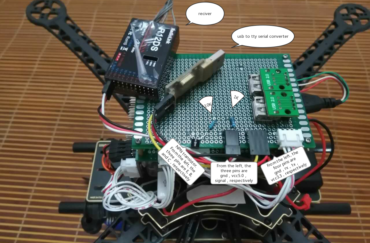
The image below shows the connections on a breadboard.