# CUAV v5 (Discontinued)
WARNING
PX4 does not manufacture this (or any) autopilot. Contact the manufacturer (opens new window) for hardware support or compliance issues.
WARNING
This flight controller has been discontinued and is no longer commercially available.
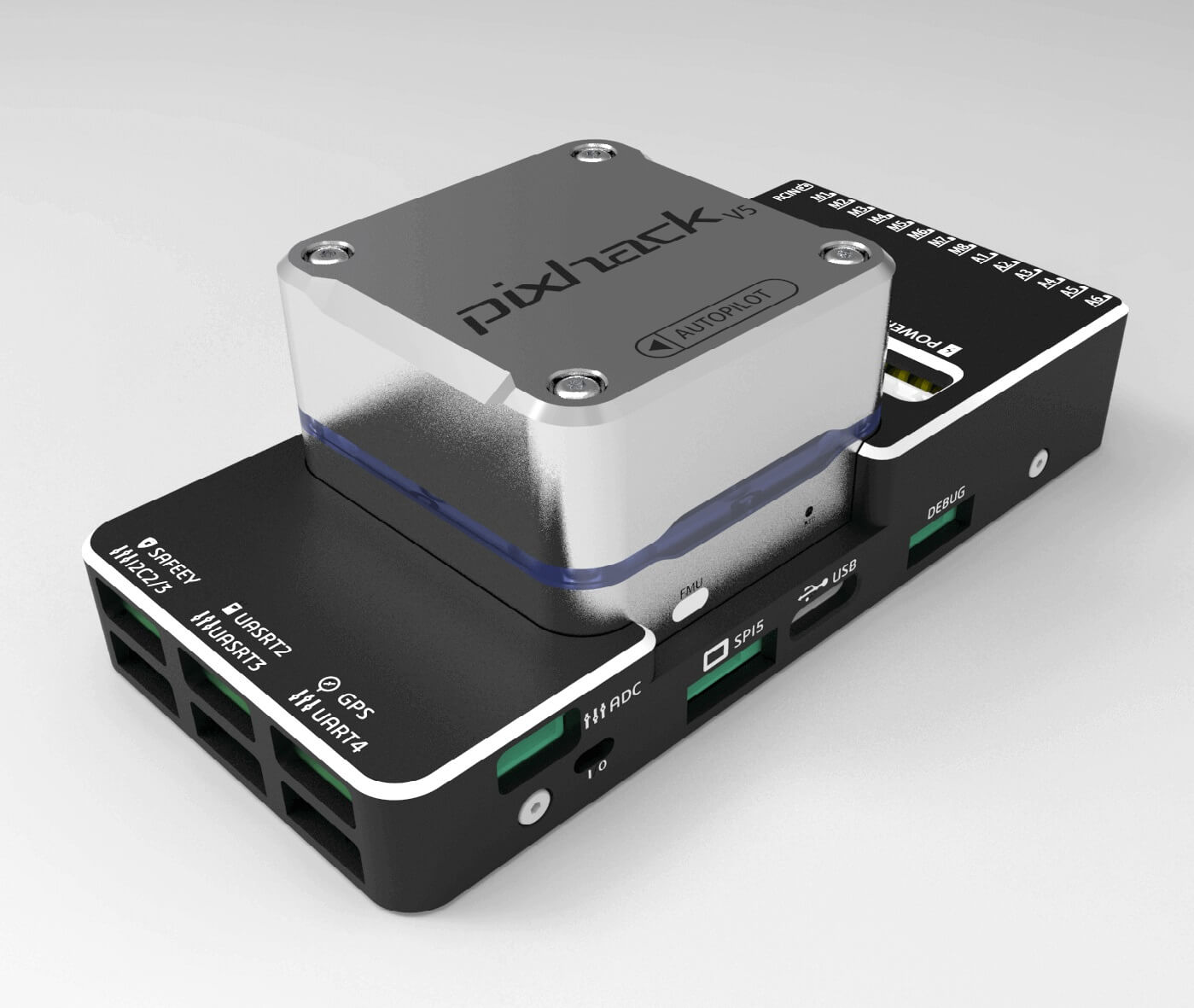
CUAV v5® (previously "Pixhack v5") is an advanced autopilot designed and made by CUAV®. The board is based on the Pixhawk-project (opens new window) FMUv5 open hardware design. It runs PX4 on the NuttX (opens new window) OS, and is fully compatible with PX4 firmware. It is intended primarily for academic and commercial developers.
# Quick Summary
Main FMU Processor: STM32F765
- 32 Bit Arm® Cortex®-M7, 216MHz, 2MB memory, 512KB RAM
IO Processor: STM32F100
- 32 Bit Arm® Cortex®-M3, 24MHz, 8KB SRAM
On-board sensors:
- Accelerometer/Gyroscope: ICM-20689
- Accelerometer/Gyroscope: BMI055
- Magnetometer: IST8310
- Barometer: MS5611
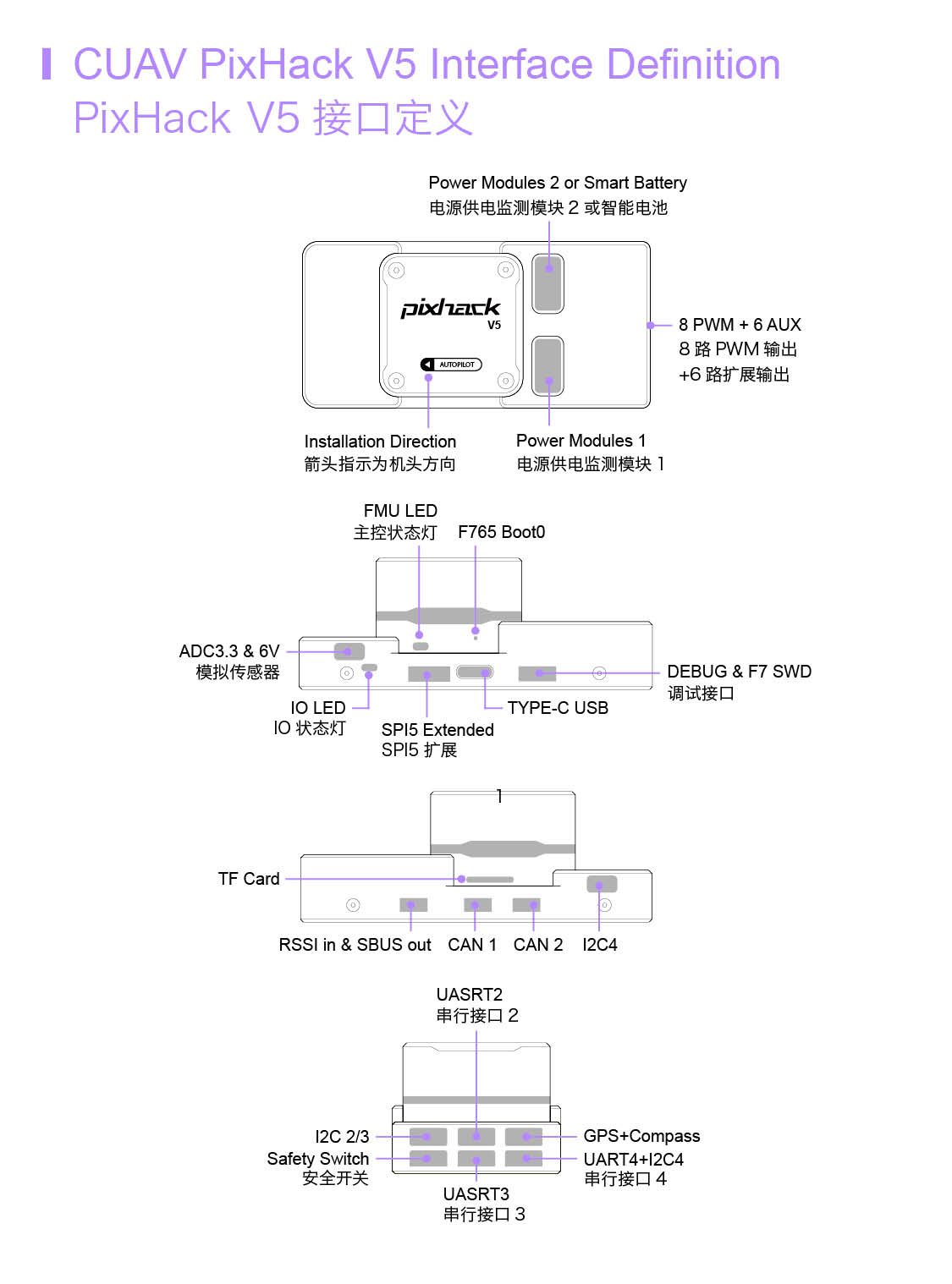
Interfaces:
- 8-14 PWM outputs (6 from IO, 8 from FMU)
- 3 dedicated PWM/Capture inputs on FMU
- Dedicated R/C input for CPPM
- Dedicated R/C input for PPM and S.Bus
- analog / PWM RSSI input
- S.Bus servo output
- 5 general purpose serial ports
- 4 I2C ports
- 4 SPI buses
- 2 CANBuses with serial ESC
- Analog inputs for voltage / current of 2 batteries
Power System:
- Power: 4.3~5.4V
- USB Input: 4.75~5.25V
- Servo Rail Input: 0~36V
Weight and Dimensions:
- Weight: 90g
- Dimensions: 44x84x12mm
Other Characteristics:
- Operating temperature: -20 ~ 80°C (Measured value)
# Purchase
Order from CUAV (opens new window).
# Connection
WARNING
The RCIN interface is limited to powering the rc receiver and cannot be connected to any power/load.
# Voltage Ratings
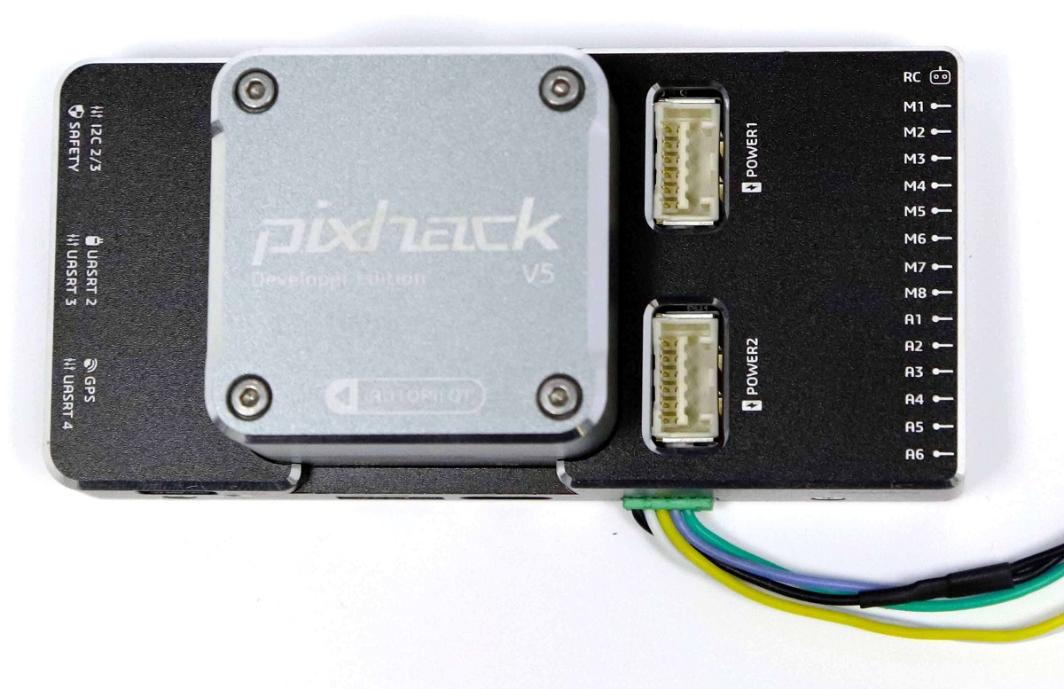
CUAV v5 can be triple-redundant on the power supply if three power sources are supplied. The three power rails are: POWER1, POWER2 and USB.
Note
The output power rails FMU PWM OUT and I/O PWM OUT (0V to 36V) do not power the flight controller board (and are not powered by it). You must supply power to one of POWER1, POWER2 or USB or the board will be unpowered.
Normal Operation Maximum Ratings
Under these conditions all power sources will be used in this order to power the system:
- POWER1 and POWER2 inputs (4.3V to 5.4V)
- USB input (4.75V to 5.25V)
# Building Firmware
TIP
Most users will not need to build this firmware! It is pre-built and automatically installed by QGroundControl when appropriate hardware is connected.
To build PX4 for this target:
make px4_fmu-v5_default
# Debug Port
The PX4 System Console and SWD interface operate on the FMU Debug port. Simply connect the FTDI cable to the Debug & F7 SWD connector. To access the I/O Debug port, the user must remove the CUAV v5 shell. Both ports have standard serial pins and can be connected to a standard FTDI cable (3.3V, but 5V tolerant).
The pinout is as shown.
| pin | CUAV v5 debug |
|---|---|
| 1 | GND |
| 2 | FMU-SWCLK |
| 3 | FMU-SWDIO |
| 4 | UART7_RX |
| 5 | UART7_TX |
| 6 | VCC |
# Serial Port Mapping
| UART | Device | Port |
|---|---|---|
| UART1 | /dev/ttyS0 | GPS |
| USART2 | /dev/ttyS1 | TELEM1 (flow control) |
| USART3 | /dev/ttyS2 | TELEM2 (flow control) |
| UART4 | /dev/ttyS3 | TELEM4 |
| USART6 | /dev/ttyS4 | TX is RC input from SBUS_RC connector |
| UART7 | /dev/ttyS5 | Debug Console |
| UART8 | /dev/ttyS6 | PX4IO |
# Peripherals
- Digital Airspeed Sensor (opens new window)
- Telemetry Radio Modules (opens new window)
- Rangefinders/Distance sensors
# Supported Platforms / Airframes
Any multicopter / airplane / rover or boat that can be controlled with normal RC servos or Futaba S-Bus servos. The complete set of supported configurations can be seen in the Airframes Reference.