# Holybro Durandal
PX4 does not manufacture this (or any) autopilot. Contact the [manufacturer](https://shop.holybro.com/) for hardware support or compliance issues.
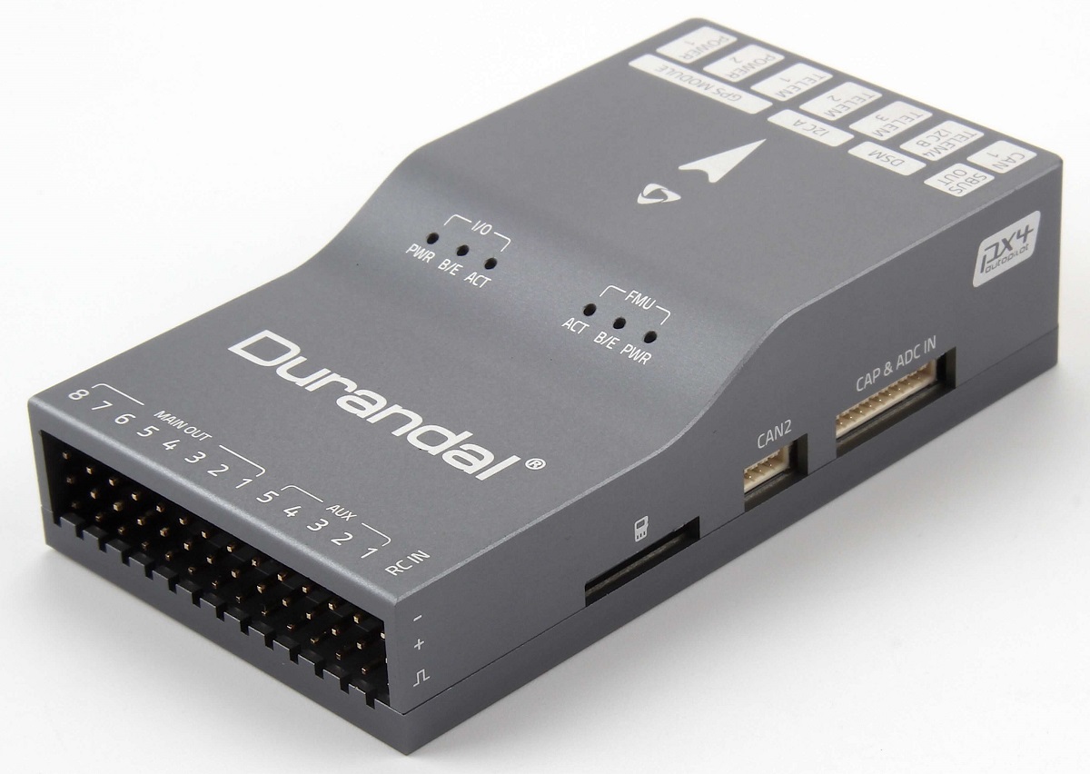
Durandal® is the latest update to the successful family of Holybro flight controllers. It was designed and developed by Holybro.
At high level, some of the key features are:
- Integrated temperature control for sensors.
- Powerful STM32H7 microcontroller running at 480MHz. 2 MB of Flash memory and 1 MB of RAM.
- New sensors with higher temperature stability.
- Internal vibration isolation system.
- Dual high-performance, low-noise IMUs on board are designed for demanding stabilization applications.
A summary of the key features, assembly, and purchase links can be found below.
注解
This flight controller is manufacturer supported.
# 概览
# Technical Specifications
- Main FMU Processor: STM32H743
- 32 Bit Arm ® Cortex® -M7, 480MHz, 2MB memory, 1MB RAM
- IO 处理器:STM32F100
- 32 Bit Arm ® Cortex® -M3, 24MHz, 8KB SRAM
- On-board sensors
- 加速度计 / 陀螺仪:ICM-20689
- Accel/Gyro: BMI088
- Mag: IST8310
- 气压计:MS5611
- GPS:ublox Neo-M8N GPS/GLONASS 接收器;集成磁力计 IST8310
# 接口
- 8-13 PWM servo outputs (8 from IO, 5 from FMU)
- FMU上有6个专用PWM/Capture输入
- Dedicated R/C input for Spektrum / DSM
- Dedicated R/C input for CPPM and S.Bus
- Dedicated S.Bus servo output and analog / PWM RSSI input
- 5个通用串行口
- 3 with full flow control
- 1 with separate 1.5A current limit
- 3 个 I2C 接口
- 4路SPI总线
- 1 internal high speed SPI sensor bus with 4 chip selects and 6 DRDYs
- 1 internal low noise SPI bus dedicated for XXX
- Barometer with 2 chip selects, no DRDYs
- 1 internal SPI bus dedicated for FRAM
- Supports temperature control located on sensor module
- 1 external SPI buses
- Up to 2 CANBuses for dual CAN
- Each CANBus has individual silent controls or ESC RX-MUX control
- 2个电池电流/电压模拟输入口
- 2 additional analog inputs
# Electrical Data
- 电源模块输出:4.9~5.5V
- Max input voltage: 6V
- 最大电流感应:120A
- USB 电源输入:4.75~5.25V
- 伺服导轨输入电压:0~36V
# Mechanical Data
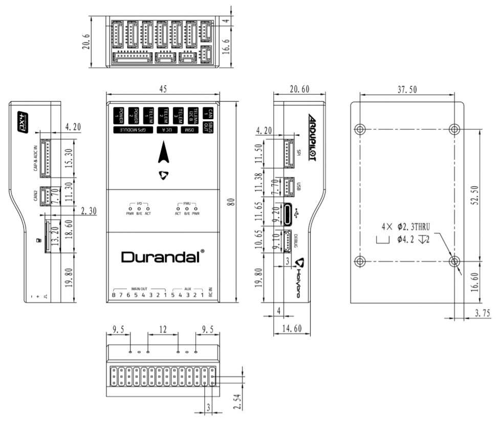
- Dimensions: 80x45x20.5mm
- 重量:68.8g
# 其它特性
- Operating temperature: ~40~85C
- Storage temperature: -40~85C
- CE
- FCC
- RoHS compliant (lead-free)
For more information see: Durandal Technical Data Sheet (opens new window).
# 采购
Order from Holybro (opens new window).
# Connections
The locations of ports/connections are shown here (and below in the pinouts section).
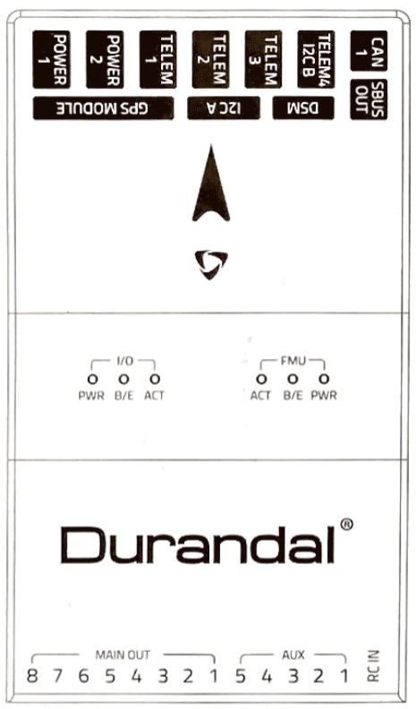
# Top
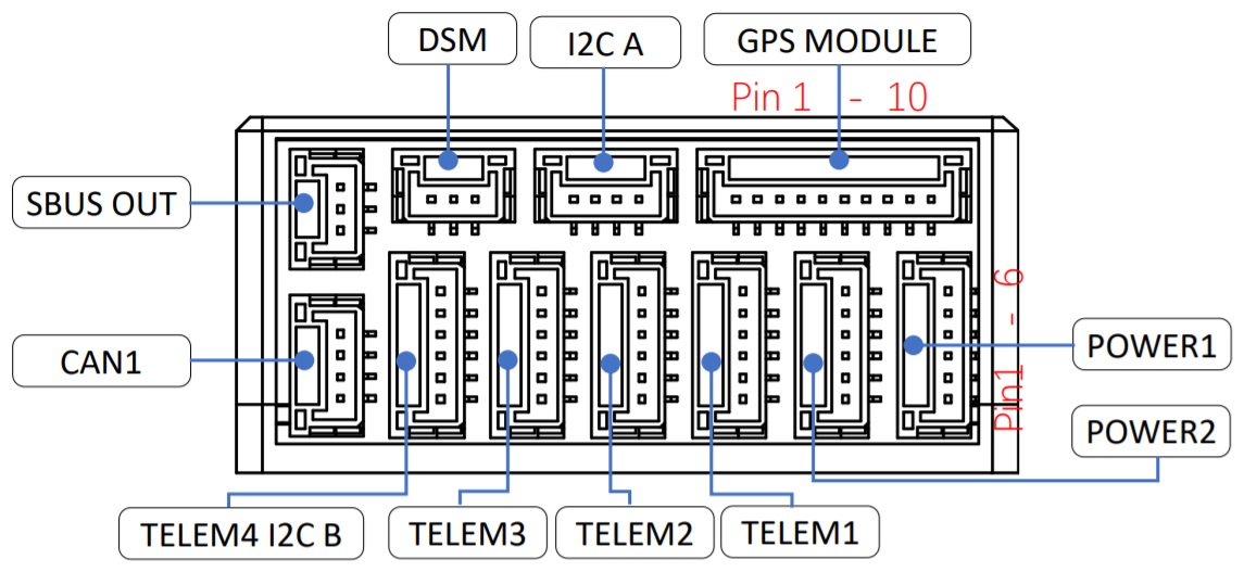
# Front
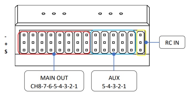
# Back
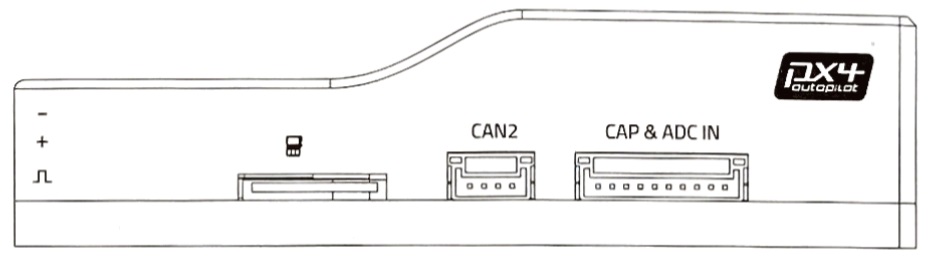
# Right
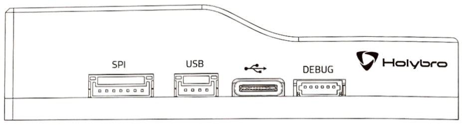
# Left
# 尺寸
All dimensions are in millimeters.
# 组装 / 设置
The Durandal Wiring Quick Start provides instructions on how to assemble required/important peripherals including GPS, Power Management Board etc.
# 编译固件
端口使用标准的串口针脚,可以连接到标准的 FTDI 连接线上(3.3V,但它有5V 耐受性),或连接到 Dronecode probe (opens new window) 上。 针脚定义使用标准的 Dronecode 调试连接器针脚定义。 有关如何连接此端口的详细信息,请参阅 接线 页面。
任何可用普通RC伺服系统或Futaba S-Bus伺服系统控制的多旋翼、固定翼、无人机、无人船。
make holybro_durandal-v1_default
# Serial Port Mapping
| UART | 设备 | Port |
|---|---|---|
| USART1 | /dev/ttyS0 | GPS1 |
| USART2 | /dev/ttyS1 | TELEM1 |
| USART3 | /dev/ttyS2 | TELEM2 |
| UART4 | /dev/ttyS3 | TELEM4/GPS2 |
| USART6 | /dev/ttyS4 | TELEM3 |
| UART7 | /dev/ttyS5 | Debug Console |
| UART8 | /dev/ttyS6 | PX4IO |
# Debug调试端口
全部可支持的机型可见 机型参考。
The port has a standard serial pinout and can be connected to a standard FTDI cable (3.3V, but it's 5V tolerant) or a Dronecode probe (opens new window). The pinout uses the standard Dronecode debug connector pinout. Please refer to the wiring page for details of how to wire up this port.
注解
No Debug port is exposed for the I/O board.
# 外部设备
# 支持的平台/机身
Any multicopter / airplane / rover or boat that can be controlled with normal RC servos or Futaba S-Bus servos.
The complete set of supported configurations can be seen in the Airframes Reference.
# 针脚定义
Durandal pinouts are listed below. These can also be downloaded from here (opens new window).
# Top Pinouts
# Front Pinouts
# SUBS Out port
| 针脚 | 信号 | 电压 |
|---|---|---|
| 1(红) | - | - |
| 2 (yellow) | SBUS_OUT/RSSI_IN | +3.3V |
| 3 (black) | GND | GND |
# DSM RC port
| 针脚 | 信号 | 电压 |
|---|---|---|
| 2 | VDD_3V3 | +3.3V |
| 2 (yellow) | DSM_IN | +3.3V |
| 3 (black) | GND | GND |
# I2C A port
| 针脚 | 信号 | 电压 |
|---|---|---|
| 2 | VCC | +5V |
| 2 (black) | SCL4 | +3.3V |
| 3 (black) | SDA4 | +3.3V |
| 4 (black) | GND | GND |
# CAN1 port
| 针脚 | 信号 | 电压 |
|---|---|---|
| 2 | VCC | +5V |
| 2 (black) | CAN H | +3.3V |
| 3 (black) | CAN L | +3.3V |
| 4 (black) | GND | GND |
# GPS 接口
| 针脚 | 信号 | 电压 |
|---|---|---|
| 2 | VCC | +5V |
| 2 (black) | TX (out) | +3.3V |
| 3 (black) | RX (in) | +3.3V |
| 4 (black) | SCL1 | +3.3V |
| 5 (black) | SDA1 | +3.3V |
| 6 (black) | SAFETY_SWITCH | +3.3V |
| 7 (black) | SAFETY_SWITCH_LED | +3.3V |
| 8 (black) | VDD_3V3 | +3.3V |
| 9 (black) | BUZZER | +5V |
| 10 (black) | GND | GND |
# TELEM4 I2CB ports
| 针脚 | 信号 | 电压 |
|---|---|---|
| 2 | VCC | +5V |
| 2 (black) | TX (out) | +3.3V |
| 3 (black) | RX (in) | - |
| 4 (black) | SCL2 | - |
| 5 (black) | SDA2 | +3.3V |
| 6 (black) | GND | GND |
# TELEM3, TELEM2, TELEM1 port
| 针脚 | 信号 | 电压 |
|---|---|---|
| 2 | VCC | +5V |
| 2 (black) | TX (out) | +3.3V |
| 3 (black) | RX (in) | +3.3V |
| 4 (black) | CTS(输入) | +3.3V |
| 5 (black) | RTS(输出) | +3.3V |
| 6 (black) | GND | GND |
# POWER port
| 针脚 | 信号 | 电压 |
|---|---|---|
| 2 | VCC | +5V |
| 2 (black) | VCC | +5V |
| 3 (black) | 电流 | +3.3V |
| 4 (black) | 电压 | +3.3V |
| 5 (black) | GND | GND |
| 6 (black) | GND | GND |
# Back Pinouts
# MAIN Out
| 针脚 | 信号 | 电压 | + | - |
|---|---|---|---|---|
| 1 | IO_CH1 | +3.3V | VDD_SERVO | GND |
| 2 | IO_CH2 | +3.3V | VDD_SERVO | GND |
| 3 | IO_CH3 | +3.3V | VDD_SERVO | GND |
| 4 | IO_CH4 | +3.3V | VDD_SERVO | GND |
| 5 | IO_CH5 | +3.3V | VDD_SERVO | GND |
| 6 | IO_CH6 | +3.3V | VDD_SERVO | GND |
| 7 | IO_CH7 | +3.3V | VDD_SERVO | GND |
| 8 | IO_CH8 | +3.3V | VDD_SERVO | GND |
# AUX Out
| 针脚 | 信号 | 电压 | + | - |
|---|---|---|---|---|
| 1 | FMU_CH1 | +3.3V | VDD_SERVO | GND |
| 2 | FMU_CH2 | +3.3V | VDD_SERVO | GND |
| 3 | FMU_CH3 | +3.3V | VDD_SERVO | GND |
| 4 | FMU_CH4 | +3.3V | VDD_SERVO | GND |
| 5 | FMU_CH5 | +3.3V | VDD_SERVO | GND |
# RC IN
| 针脚 | 信号 | 电压 |
|---|---|---|
| S | SBUS_IN/PPM_IN | +3.3V |
| + | VCC | +5V |
| - | GND | GND |
# Right-side Pinouts
# CAN2 port
| 针脚 | 信号 | 电压 |
|---|---|---|
| 2 | VCC | +5V |
| 2 (black) | CAN H | +3.3V |
| 3 (black) | CAN L | +3.3V |
| 4 (black) | GND | GND |
# CAP & ADC IN port
| 针脚 | 信号 | 电压 |
|---|---|---|
| 2 | VCC | +5V |
| 2 (black) | FMU_CAP6 | +3.3V |
| 3 (black) | FMU_CAP5 | +3.3V |
| 4 (black) | FMU_CAP4 | +3.3V |
| 5 (black) | FMU_CAP3 | +3.3V |
| 6 (black) | FMU_CAP2 | +3.3V |
| 7 (black) | FMU_CAP1 | +3.3V |
| 8 (black) | ADC1_SPARE_1 | +3.3V ++ |
| 9 (black) | ADC1_SPARE_2 | +6.6V ++ |
| 10 (black) | GND | GND |
注意
++ Sensors connected to pins 8, 9 must not send a signal exceeding the indicated voltage.
# Left-side Pinouts
# DEBUG port
| 针脚 | 信号 | 电压 |
|---|---|---|
| 2 | VT | +3.3V |
| 2 (black) | TX | +3.3V |
| 3 (black) | RX | +3.3V |
| 4 (black) | SWDIO | +3.3V |
| 5 (black) | SWCLK | +3.3V |
| 6 (black) | GND | GND |
# SPI port
| 针脚 | 信号 | 电压 |
|---|---|---|
| 2 | VCC | +5V |
| 2 (black) | SCK | +3.3V |
| 3 (black) | MISO | +3.3V |
| 4 (black) | MOSI | +3.3V |
| 5 (black) | CS1 | +3.3V |
| 6 (black) | CS2 | +3.3V |
| 7 (black) | GND | GND |
# USB port
| 针脚 | 信号 | 电压 |
|---|---|---|
| 2 | VBUS | +5V |
| 2 (black) | DM | +3.3V |
| 3 (black) | DP | +3.3V |
| 4 (black) | GND | GND |