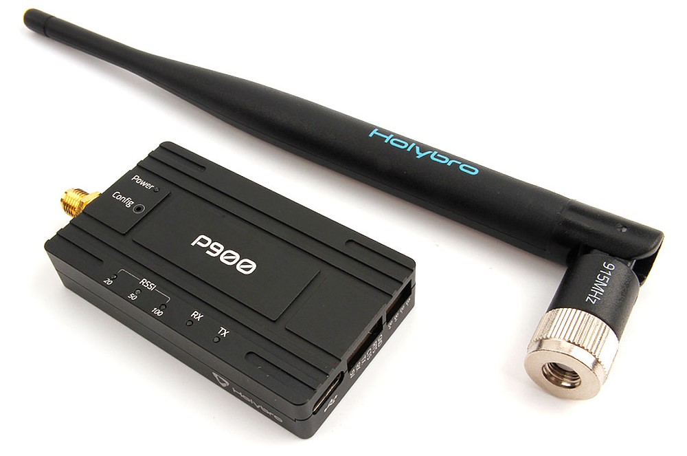
# Holybro Microhard P900 Radio
The Holybro Microhard P900 Radio (opens new window) integrates the Microhard Pico Serial (opens new window) P900 RF module, which is capable of delivering high-performance wireless serial communications in robust and secure mesh, point-to-point or point-to-multipoint topologies. It enables MAVLink communication between a radio on a vehicle and a GCS.
This radio operate within the 902-928 MHz ISM frequency band, using frequency hopping spread spectrum (FHSS) technology, providing reliable wireless asynchronous data transfer between most equipment types which employ a serial interface. The radio may be configured as a primary coordinator, secondary coordinator, standby coordinator or remote in a mesh topology, or a master, repeater or remote in a PP or PMP topology.
This versatility is very convenient for the user. This radio is configured using AT commands through the data port or using PicoConfig application through the diagnosis port.
The transmit power is software selectable from 100mW to 1W, with range up to 40 miles. A single ground station radio can be used to communicate with multiple vehicles using point to multi-point or mesh. Vehicles must have different MAVLINK IDs.
# Features
- USB Type-C port, integrated USB to UART converter
- 6-position JST-GH connector, can be directly connected to the TELEM port on various Pixhawk-standard flight controllers such Pixhawk 4 & Pixhawk 5X
- High voltage BEC onboard, Support DC7~35V voltage supply
- UART transmission & Three-stage RSSI LED indicator
- Transmission within a public, license-exempt band of the radio spectrum
- Transparent, low latency link rates up to 276 Kbps
- Supports a robust true Mesh operation with auto-routing
- 32 bits of CRC, selectable retransmission and forward error correction
- Separate diagnostics port, transparent remote diagnostics and online network control
# Purchase:
# Specification

# Connecting
# Vehicle Radio
This radio comes with a 6-Pin JST GH cable that can be connected to the TELEM1 port on flight controllers that are compliant with the Pixhawk connector standard.
The radio must be separately powered via the 4-pin JST-GH XT30 power cable (7-35VDC).
# Ground Station Radio
This radio has a internal USB to UART converter, the ground radio can be connected to the ground station via USB C. The radio must be separately powered via the XT30 power cable (7-35VDC).
# Setup/Configuration
Holybro Microhard P900 Radios have been configured to point-to-point operating mode and 57600 serial baud rate in the factory.
This allows them to connect to the PX4 TELEM1 port and QGroundControl without any further configuration.
Note
You can use a different baud rate, mode or flight controller port. The only "requirement" is that the ground radio, air radio, PX4, and QGroundControl must all be set to the same baud rate.
Microhard Serial Telemetry Radios > Configuration explains how to configure the radios, QGroundControl, and PX4.
In order to configure the radios using the PicoConfig application (as described in the link above) it must be connected through the diagnostic port:

The diagnostic port uses a 4-position JST SH connector. If you use PicoConfig application or special diagnostic commands to config the radio, you should connect to this port. The diagnostic port is 3.3V logic level compatible. A USB-to-serial board is needed for connecting the radio to your computer. You can purchase a Holybro UART to USB Converter (opens new window).
Pico Config will automatically detect and connect to the configuration port. Adjust the settings so that the baud rate matches PX4 (and the ground station).
Holding the Config button while powering-up the radio will boot the unit into COMMAND mode: the default serial interface will be active and temporarily set to operate at its default serial settings of 9600/8/N/1.
Note that it is also possible to configure the radios using AT commands through the data port.
# Default Configuration
The default radio configuration as shipped is shown in PicoConfig below (you may need to reconfigure them as shown after firmware update or resetting the radio).


In point-to-point operating modes, there must be a master to provide network synchronization for the system, so one radio should be configured to PP master and another should be configured to PP remote.
# Status LED

The P900 Radio has 6 status LEDs: three are blue, two are orange, and one is green. The meanings of the different LEDs are:
- Power LED(green)
- This LED will illuminate when the P900 Radio is connected to a power source (7-35VDC).
- TX LED (orange)
- When illuminated, this LED indicates that the Radio is transmitting data over the air.
- RX LED (orange)
- This LED indicates that the Radio is synchronized and has received valid packets.
- RSSI LEDs (3x Blue)
- As the received signal strength increases, starting with the furthest left, the number of active
- RSSI LEDs increases. Signal strength is calculated based on the last four valid received packets with correct CRC. The value of RSSI is reported in S123.


# Pinout
# Diagnosis Port
| Pin | Signal | Voltage |
|---|---|---|
| 1 | NC | -- |
| 2 (black) | RX | +3.3V |
| 3 (black) | TX | +3.3V |
| 4 (black) | GND | GND |
# Data Port
| Pin | Signal | Voltage |
|---|---|---|
| 1 (red) | NC | -- |
| 2 (black) | RX | +3.3V |
| 3 (black) | TX | +3.3V |
| 4 (black) | CTS | +3.3V |
| 5 (black) | RTS | +3.3V |
| 6 (black) | GND | GND |
# Power Port
| Pin | Signal | Voltage |
|---|---|---|
| 1(red) | BAT+ | 7-35V |
| 2 (red) | BAT+ | 7-35V |
| 3 (black) | BAT- | GND |
| 4 (black) | BAT- | GND |

# Dimensions

# Power Consumption
- Supply voltage: DC7~35V from 4-pin JST-GH to XT30 (included)
- Transmit current: 200 mA/7V at 20dBm
- 350mA/7V at 27dBm
- 800 mA/7V at 30dBm
- Receive current: 100 mA
- Weight: 42g (without antenna)