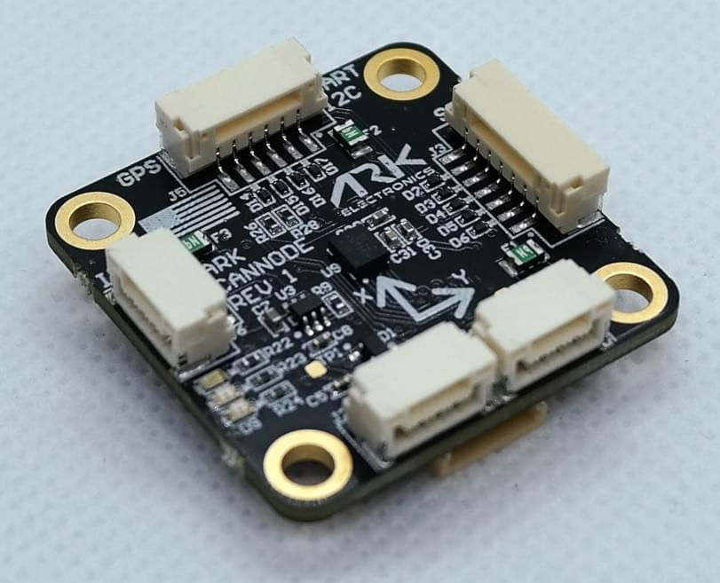
# ARK CANnode
ARK CANnode (opens new window) is an open source generic UAVCAN node that includes a 6 degree of freedom IMU. Its main purpose is to enable the use of non-CAN sensors (I2C, SPI, UART) on the CAN bus. It also has PWM outputs to expand a vehicle's control outputs in quantity and physical distance.
# Where to Buy
Order this module from:
# Specifications
- Open Source Schematic and BOM (opens new window)
- Runs PX4 Open Source Firmware (opens new window)
- Supports UAVCAN Firmware Updating
- Dynamic UAVCAN node enumeration
- Sensors
- PixArt PAW3902 Optical Flow Sensor
- Tracks under super low light condition of >9 lux
- Wide working range from 80mm up to 30m
- Up to 7.4 rad/s
- 40mW IR LED built onto board for improved low light operation
- Broadcom AFBR-S50LV85D Time-of-Flight Distance Sensor
- Integrated 850 nm laser light source
- Field-of-View (FoV) of 12.4° x 6.2° with 32 pixels
- Typical distance range up to 30m
- Operation of up to 200k Lux ambient light
- Works well on all surface conditions
- Transmitter beam of 2° x 2° to illuminate between 1 and 3 pixels
- Bosch BMI088 6-Axis IMU or Invensense ICM-42688-P 6-Axis IMU
- PixArt PAW3902 Optical Flow Sensor
- STM32F412CGU6 MCU
- 1MB Flash
- Two Pixhawk Standard CAN Connectors
- 4 Pin JST GH
- Pixhawk Standard I2C Connector
- 4 Pin JST GH
- Pixhawk Standard UART/I2C Connector (Basic GPS Port)
- 6 Pin JST GH
- Pixhawk Standard SPI Connector
- 7 Pin JST GH
- PWM Connector
- 10 Pin JST JST
- 8 PWM Outputs
- Matches Pixhawk 4 PWM Connector Pinout
- Pixhawk Standard Debug Connector
- 6 Pin JST SH
- Small Form Factor
- 3cm x 3cm x 1.3cm
- LED Indicators
- USA Built
- Power Requirements
- 5V
- Current dependent on connected peripherals
# Wiring/Connecting
The ARK CANnode is connected to the CAN bus using a Pixhawk standard 4 pin JST GH cable. Multiple CAN nodes can be connected by plugging additional nodes into the ARK CANnode's second CAN connector.
General instructions for UAVCAN wiring can also be found in UAVCAN > Wiring.
For connecting sensors to the ARK CANnode, refer to the individual sensor's documentation on connecting to a Pixhawk Flight Controller.
# PX4 Setup
# Enabling UAVCAN
In order to use the ARK CANnode board, connect it to the Pixhawk CAN bus and enable the UAVCAN driver by setting parameter UAVCAN_ENABLE to 2 for dynamic node allocation (or 3 if using UAVCAN ESCs) (UAVCAN configuration is explained in more detail in UAVCAN > PX4 Configuration.
The steps are:
- In QGroundControl set the parameter UAVCAN_ENABLE to
2or3and reboot (see Finding/Updating Parameters). - Connect ARK CANnode CAN to the Pixhawk CAN.
Once enabled, the module will be detected on boot.
# PX4 Configuration
Depending on the sensors that are connected to the ARK CANnode, you will need to enable each subscriber on the flight controller under the parameters UAVCAN_SUB_* (such as UAVCAN_SUB_ASPD, UAVCAN_SUB_BARO etc.).
On the ARK CANnode, you may need to configure the following parameters:
| Parameter | Description |
|---|---|
| CANNODE_TERM | CAN built-in bus termination. |
# LED Meanings
You will see both red and blue LEDs on the ARK CANnode when it is being flashed, and a solid blue LED if it is running properly.
If you see a solid red LED there is an error and you should check the following:
- Make sure the flight controller has an SD card installed.
- Make sure the ARK CANnode has
ark_cannode_canbootloaderinstalled prior to flashingark_cannode_default. - Remove binaries from the root and ufw directories of the SD card and try to build and flash again.
# Building ARK CANnode Firmware
ARK CANnode is sold with a recent firmware build. Developers who want to update to the very latest version can build and install it themselves using the normal PX4 toolchain and sources.
The steps are:
Install the PX4 toolchain.
Clone the PX4-Autopilot sources, including ARK CANnode, using git:
git clone https://github.com/PX4/PX4-Autopilot --recursive
cd PX4-Autopilot
Build the ARK CANnode firmware:
make ark_cannode_defaultThat will have created a binary in build/ark_cannode_default named XX-X.X.XXXXXXXX.uavcan.bin. Put this binary on the root directory of the flight controller’s SD card to flash the ARK CANnode. Next time you power your flight controller with the SD card installed, ARK CANnode will automatically be flashed and you should notice the binary is no longer in the root directory and there is now a file named 83.bin in the ufw directory of the SD card.
Note
The ARK CANnode will not boot if there is no SD card in the flight controller when powered on.
# Updating ARK CANnode Bootloader
The ARK CANnode comes with the bootloader pre-installed. You can, however, rebuild and reflash it within the PX4-Autopilot environment.
The steps are:
- Build the ARK CANnode bootloader firmware:
make ark_cannode_canbootloaderNote
This will setup your
launch.jsonfile if you are in VS code. If using the Black Magic Probe and VS code, make sure to updateBMPGDBSerialPortwithin this file to the correct port that your debugger is connected to. On MacOS, the port name should look something likecu.usbmodemE4CCA0E11. - Connect to your ARK CANnode to any Serial Wire Debugging (SWD) device that supports use of GNU Project Debugger (GDB), such as the Black Magic Probe and then connect power to your ARK CANnode via one of the CAN ports.
- Flash the ARK CANnode with
ark_cannode_canbootloader. To do so in VS Code, you should seeCMake: [ark_cannode_canbootloader]: Readyon the bottom bar of VS Code, indicating what you are flashing. You then flash the bootloader by selectingStart Debuggingin the Run and Debug window of VS Code and then selecting Continue after the first breakpoint. - With the bootloader flashed, you are ready to build and flash the ARK CANnode firmware
ark_cannode_defaultas outlined above.