# 신규 기체 구성 추가
PX4는 고정된 기체 구성을 기체의 시작점으로 사용합니다. 구성은 ROMFS/px4fmu_common/init.d (opens new window) 폴더에 저장된 구성 파일에 정의됩니다.
https://github.com/PX4/PX4-Autopilot/blob/master/Tools/px4airframes/srcparser.py
자체 구성을 만들고 싶지 않은 개발자는 맞춤 시스템 시작 페이지에 설명된 대로 microSD 카드의 텍스트 파일을 사용하여 기존 구성을 맞춤 설정할 수 있습니다.
Note
구성 파일에서 설정하는 매개변수를 결정하려면, 먼저 일반 기체를 할당하고 차량을 조정한 다음 param show-for-airframe을 사용하여 변경된 매개변수를 나열합니다.
# 구성 파일 개요
The configuration file consists of several main blocks:
- 기체 문서(기체 정의서 및 QGroundControl에서 사용됨).
- Airframe-specific parameter settings, including tuning gains
- 시작해야 하는 컨트롤러 및 앱(예: 멀티콥터 또는 고정익 컨트롤러, 지면 탐지기 등)
- The physical configuration of the system (e.g. a plane, wing or multicopter) and geometry. Geometry may be specified using a mixer file or using control allocation parameters (from PX4 v1.13).
이러한 측면은 대부분 독립적이므로, 많은 구성이 기체의 동일한 물리적 레이아웃을 공유하고 동일한 응용 프로그램을 시작하며 튜닝 이득이 가장 차이가 납니다.
Note
새 기체 파일은 클린 빌드(make clean 실행) 이후에만, 빌드 시스템에 자동으로 추가됩니다.
# 설정 파일
일반적인 구성 파일은 아래와 같습니다(원본 파일은 여기 (opens new window)).
첫 번째 섹션은 기체 문서입니다. 이것은 기체 정의서와 QGroundControl에서 사용됩니다.
#!/bin/sh
#
# @name Wing Wing (aka Z-84) Flying Wing
#
# @url https://docs.px4.io/master/en/frames_plane/wing_wing_z84.html
#
# @type Flying Wing
# @class Plane
#
# @output MAIN1 left aileron
# @output MAIN2 right aileron
# @output MAIN4 throttle
#
# @output AUX1 feed-through of RC AUX1 channel
# @output AUX2 feed-through of RC AUX2 channel
# @output AUX3 feed-through of RC AUX3 channel
#
# @maintainer Lorenz Meier <lorenz@px4.io>
#
# @board px4_fmu-v2 exclude
# @board bitcraze_crazyflie exclude
#
다음 섹션은 튜닝 게인을 포함하여, 차량 매개변수를 지정합니다.
. ${R}etc/init.d/rc.fw_defaults

param set-default BAT_N_CELLS 2
param set-default FW_AIRSPD_MAX 15
param set-default FW_AIRSPD_MIN 10
param set-default FW_AIRSPD_TRIM 13
param set-default FW_R_TC 0.3
param set-default FW_P_TC 0.3
param set-default FW_L1_DAMPING 0.74
param set-default FW_L1_PERIOD 16
param set-default FW_LND_ANG 15
param set-default FW_LND_FLALT 5
param set-default FW_LND_HHDIST 15
param set-default FW_LND_HVIRT 13
param set-default FW_LND_TLALT 5
param set-default FW_THR_LND_MAX 0
param set-default FW_PR_FF 0.35
param set-default FW_RR_FF 0.6
param set-default FW_RR_P 0.04

param set-default PWM_MAIN_DISARM 1000
기체 유형 설정(MAV_TYPE (opens new window)):
# Configure this as plane
set MAV_TYPE 1
Set the mixer to use (if control allocation is not enabled):
# Set mixer
set MIXER wingwing
PWM 출력을 구성합니다(구동/활성화할 출력 및 레벨 지정).
set PWM_OUT 4
WARNING
채널을 되돌리려면, RC 송신기나 RC1_REV와 같이 사용하지 마십시오. 채널은 수동 모드에서 비행시에만 반전되며, 자동 조종 비행 모드로 전환하면 채널 출력이 여전히 잘못됩니다(RC 신호만 반전됨). 따라서, 올바른 채널 할당을 위해 PWM 신호를 PWM_MAIN_REV1(예: 채널 1의 경우)으로 변경하거나 해당 믹서에서 출력 스케일링의 부호를 변경합니다(아래 참조).
# 믹서 파일
Note
Mixer files will be replaced by Control Allocation parameters in the next version (after PX4 v1.13).
You can enable control allocation in PX4 v1.13 by setting SYS_CTRL_ALLOC=1. If enabled, the geometry may then be defined using CA_* parameters in the airframe configuration file, as shown in 13200_generic_vtol_tailsitter (opens new window).
Note
개념 > 믹싱을 먼저 참고하십시오. 이것은 믹서 파일을 해석에 필요한 배경 정보를 제공합니다.
mixer files describe the physical configuration of the system, and are stored in the ROMFS/px4fmu_common/mixers (opens new window) folder.
일반적인 믹서 파일은 아래에 나와 있습니다(원본 파일은 여기 (opens new window)). 믹서 파일 이름(이 경우 wingwing.main.mix)은 기체 유형(wingwing), 출력 유형(.main 또는 .aux), 그리고 믹서 파일(.mix)에 대한 중요한 정보를 제공합니다.
믹서 파일에는 여러 코드 블록이 포함되어 있으며, 각 블록은 하나의 액추에이터 또는 ESC를 나타냅니다. 예를 들어 2개의 서보와 1개의 ESC, 믹서 파일에는 3개의 코드 블록이 포함됩니다.
Note
서보/모터의 플러그는 이 파일의 믹서 순서대로 이동합니다.
따라서 MAIN1은 왼쪽 에일러론, MAIN2는 오른쪽 에일러론, MAIN3은 비어 있고(Z: 제로 믹서 참고) MAIN4는 스로틀입니다(일반적인 고정익은 출력 4에서 스로틀을 유지하기 위하여).
믹서는 -1..+1에 해당하는 -10000에서 10000까지의 정규화된 단위로 인코딩됩니다.
M: 2
O:      10000  10000      0 -10000  10000
S: 0 0  -6000  -6000      0 -10000  10000
S: 0 1   6500   6500      0 -10000  10000
여기서 왼쪽에서 오른쪽으로 각 숫자는 다음을 의미합니다.
- M: 2개의 제어 입력에 대한 2개의 스케일러를 나타냅니다. 믹서가 수신할 컨트롤 입력의 수를 나타냅니다.
- O: 출력 스케일링(음수에서 *1, 양수에서 *1), 오프셋(여기서는 0) 및 출력 범위(여기서는 -1..+1)를 나타냅니다.
- PWM 신호를 반전시키려면, 출력 스케일링 부호를 변경합니다.
O: -10000 -10000 0 -10000 10000 - 이 줄은 기본 크기 조정을 지정하는 경우 완전히 생략할 수 있습니다(및 반드시 생략해야 함).
O: 10000 10000 0 -10000 10000
- PWM 신호를 반전시키려면, 출력 스케일링 부호를 변경합니다.
- S: 첫 번째 입력 스케일러를 나타냅니다. 제어 그룹 #0(Flight Control)과 첫 번째 입력(roll)에서 입력을 받습니다. 롤 제어 입력의 크기를 * 0.6으로 조정하고 부호를 되돌립니다(-0.6은 축척 단위로 -6000이 됨). 오프셋을 적용하지 않고(0) 전체 범위(-1..+1)로 출력합니다.
- S: 두 번째 입력 스케일러를 나타냅니다. 제어 그룹 #0(비행 제어) 및 두 번째 입력(피치)에서 입력을 받습니다. 피치 제어 입력 * 0.65를 조정합니다. 오프셋을 적용하지 않고(0) 전체 범위(-1..+1)로 출력합니다.
Note
간단히 요약하면, 이 믹서의 출력은 SERVO = ( (롤 입력 * -0.6 + 0) * 1 + (피치 입력 * 0.65 + 0) * 1 ) * 1 + 0입니다.
무대 뒤에서 두 스케일러가 모두 추가되어 비행 날개의 경우 제어 표면이 롤에서 최대 60% 편향, 피치에서 65% 편향을 취합니다.
믹서의 최종 형태는 다음과 같습니다.
Delta-wing mixer for PX4FMU
===========================

Designed for Wing Wing Z-84

This file defines mixers suitable for controlling a delta wing aircraft using
PX4FMU. The configuration assumes the elevon servos are connected to PX4FMU
servo outputs 0 and 1 and the motor speed control to output 3. Output 2 is
assumed to be unused.

Inputs to the mixer come from channel group 0 (vehicle attitude), channels 0
(roll), 1 (pitch) and 3 (thrust).

See the README for more information on the scaler format.

Elevon mixers
-------------
Three scalers total (output, roll, pitch).

The scaling factor for roll inputs is adjusted to implement differential travel
for the elevons.

This first block of code is for Servo 0...

M: 2
O:      10000  10000      0 -10000  10000
S: 0 0  -6000  -6000      0 -10000  10000
S: 0 1   6500   6500      0 -10000  10000

And this is for Servo 1...

M: 2
O:      10000  10000      0 -10000  10000
S: 0 0  -6000  -6000      0 -10000  10000
S: 0 1  -6500  -6500      0 -10000  10000

Note that in principle, you could implement left/right wing asymmetric mixing, but in general the two blocks of code will be numerically equal, and just differ by the sign of the third line (S: 0 1), since to roll the plane, the two ailerons must move in OPPOSITE directions.
The signs of the second lines (S: 0 0) are identical, since to pitch the plane, both servos need to move in the SAME direction.

Output 2
--------
This mixer is empty.

Z:

Motor speed mixer
-----------------
Two scalers total (output, thrust).

This mixer generates a full-range output (-1 to 1) from an input in the (0 - 1)
range.  Inputs below zero are treated as zero.

M: 1
O:      10000  10000      0 -10000  10000
S: 0 3      0  20000 -10000 -10000  10000
# 새 기체 그룹 추가
기체 "그룹"은 QGroundControl (opens new window) 및 기체 정의서 문서(PX4 DevGuide 및 PX4 UserGuide)에서 선택하기 위하여 유사한 기체들을 그룹화합니다. 모든 그룹에는 그룹화된 기체에 대한 공통 지오메트리, 모터 수, 및 모터 회전 방향을 나타내는 이름과 연관된 svg 이미지가 있습니다.
QGroundControl에서 사용하는 기체 메타데이터 파일과 문서 소스 코드는 make airframe_metadata 빌드 명령을 사용하여 스크립트를 통하여 기체 설명에서 생성됩니다.
기존 그룹에 속한 새 기체의 경우 다음 위치 ROMFS/px4fmu_common/init.d (opens new window)에 있는 기체 설명에 문서를 제공하는 것 외에는 아무 것도 할 필요가 없습니다.
기체가 새 그룹을 위한 것이라면, 추가로 다음 작업을 수행하여야 합니다.
- 그룹에 대한 svg 이미지를 사용자 가이드 문서에 추가합니다(이미지가 제공되지 않은 경우 자리 표시자 이미지가 표시됨): assets/airframes/types (opens new window)
- srcparser.py (opens new window) 메소드
GetImageName()에서 새 그룹 이름과 이미지 파일 이름 간의 매핑을 추가합니다(아래 패턴을 따릅니다).def GetImageName(self): """ Get parameter group image base name (w/o extension) """ if (self.name == "Standard Plane"): return "Plane" elif (self.name == "Flying Wing"): return "FlyingWing" ... ... return "AirframeUnknown" - QGroundControl을 업데이트 합니다.
- 그룹에 대한 svg 이미지를 src/AutopilotPlugins/Common/images (opens new window)에 추가합니다.
- 아래 패턴에 따라 svg 이미지에 대한 참조를 qgcimages.qrc (opens new window)에 추가합니다.
<qresource prefix="/qmlimages">
   ...
   <file alias="Airframe/AirframeSimulation">src/AutoPilotPlugins/Common/Images/AirframeSimulation.svg</file>
   <file alias="Airframe/AirframeUnknown">src/AutoPilotPlugins/Common/Images/AirframeUnknown.svg</file>
   <file alias="Airframe/Boat">src/AutoPilotPlugins/Common/Images/Boat.svg</file>
   <file alias="Airframe/FlyingWing">src/AutoPilotPlugins/Common/Images/FlyingWing.svg</file>
   ...
Note
나머지 기체 메타데이터는 펌웨어에 자동으로 포함되어야 합니다(srcparser.py가 업데이트되면).
# 게인 튜닝
구성 파일에 지정될 매개변수를 조정하는 방법을 설명합니다.
# QGroundControl에 신규 기체 추가
신규 기체를 QGroundControl 기체 구성 섹션에 사용할 수 있도록 하려면:
- 깨끗한 빌드 만들기(예:
make clean을 실행한 다음make px4_fmu-v5_default실행) - QGC를 열고 아래와 같이 **맞춤 펌웨어 파일...**을 선택합니다.
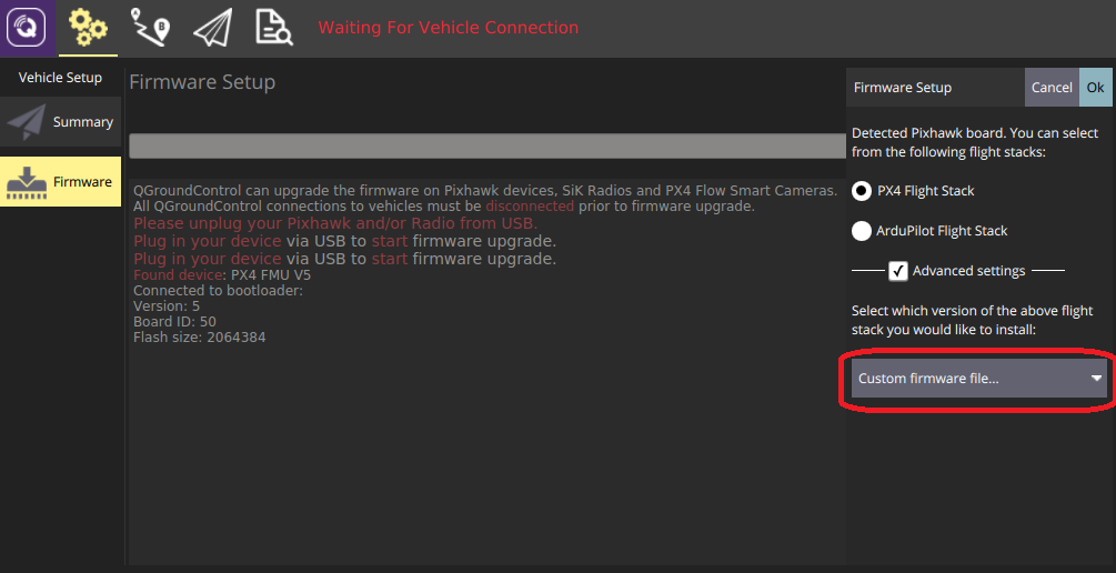
플래시할 .px4 펌웨어 파일을 선택하라는 메시지가 표시됩니다(이 파일은 압축된 JSON 파일이며 기체 메타데이터가 포함되어 있습니다).
- 빌드 폴더로 이동하여 펌웨어 파일을 선택합니다(예: PX4-Autopilot/build/px4_fmu-v5_default/px4_fmu-v5_default.px4).
- 확인을 눌러, 펌웨어 플래시를 시작합니다.
- QGroundControl을 재시작합니다.
QGroundControl에서 신규 기체를 선택할 수 있습니다.
← 시리얼 포트 매핑 장치 드라이버 개발 →