# PWM 서보 및 ESC (모터 컨트롤러)
PWM 기반 브러시리스 모터 컨트롤러, 서보를 연결 방법과 전원 공급 방법을 설명합니다.
# ESC 연결 개요
각 PWM ESC에는 최소한 다음과 같은 전선들을 가지고 있습니다.
- Power VBAT (일반적으로 두껍고 빨간색)
- Power GND (보통 두껍고 검정색)
그리고 서보 플러그에서:
- PWM 신호 (일반적으로 흰색 또는 노란색)
- GND (일반적으로 검정색 또는 갈색)
서보 플러그에는 +5V 와이어 (일반적으로 빨간색 또는 주황색)도 있을 수 있습니다. 이 와이어의 목적과 연결 방법은 ESC와 기체 유형에 따라 달라집니다.
TIP
일부 경우 (아래 참조) +5V 라인이 필요하지 않습니다. +5V 라인을 절단하는 대신 해당 핀용 서보 커넥터 플라스틱 하우징의 잠금 탭을 부드럽게 들어 올린 다음 (예 : 커터 블레이드 또는 소형 스크루 드라이버 사용) 핀을 빼낼 수 있습니다. 전기 절연 테이프로 분리하고 서보 케이블에 테이프로 붙입니다. 이렇게하면 나중에 필요한 경우 와이어를 쉽게 취소할 수 있습니다.
# 전원 연결
항상 Power VBAT 및 GND를 배터리에 연결하고, PWM 신호 및 GND를 서보 플러그에서 모터로 연결하십시오.
TIP
신호 접지를 연결할 필요가 없는 설정은 없습니다.
+5V 와이어 (있는 경우)에 대한 연결은 ESC/기체에 따라 달라집니다.
# 고정익 / VTOL
고정익(또는 VTOL) ESC에서 +5V 라인은 일반적으로 배터리제거회로(BEC)의 출력을 제공합니다.
이것은 Pixhawk 서보 레일에 연결되어 플랩, 에일러론 등의 서보에 전원을 공급에 사용할 수 있습니다.
Note
자동조종장치의 전원공급장치에서 서보 또는 ESC에 전원을 공급하는 것은 안전하지 않습니다.
Note
자동조종장치의 전원공급장치에서 서보 또는 ESC에 전원을 공급하는 것은 안전하지 않습니다.
- 경험상, Pixhawk 서보 레일에는 하나의 BEC 출력만 연결하여야 합니다. 여러 +5V 출력을 레일에 연결할 수 있지만, ESC 모델에 따라 다릅니다.
# 멀티콥터
멀티 콥터에서 +5V 라인이 없거나 (있는 경우) 연결되지 않을 수 있습니다.
- 멀티 콥터는 종종 서보가 필요하지 않으므로, Pixhawk 서보 레일에 전원을 공급할 필요가 없습니다 (모터는 일반적으로 배전 보드에서 별도로 전원이 공급됨).
- 와이어를 서보 레일에 연결하여도 단점이나 장점은 없습니다.
- DJI ESC는 일반적으로 이 와이어가 포함되어 있지만, 연결되어 있지는 않습니다.
# 광절연 ESC
BEC가 없는 광절연 ESC에서 +5V 라인을 연결하고 전원을 공급해야 할 수 있습니다 (ESC 마이크로 컨트롤러에 전원을 공급하기 위하여). 이 경우 와이어는 일반적으로 비행 콘트롤러 서보 레일에 연결되며, 서보 레일은 추가 BEC에서 전원을 공급하여야 합니다.
# PX4 Configuration
Configure the outputs using the following parameters:
- PWM_MAIN_RATE (IO) and/or PWM_AUX_RATE (FMU): Set to the highest frame rate supported by the connected ESC, in Hz.
- PWM_MAIN_MIN/PWM_AUX_MIN and PWM_MAIN_MAX/PWM_AUX_MAX: Set to the normal PWM range, nominally
1000to2000. - DSHOT_CONFIG: Set to
0in order to disable DShot.
Then perform ESC Calibration.
Additional PX4 PWM configuration parameters can be found here: PWM Outputs.
# 문제 해결
Pixhawk is compatible with all PWM ESCs on the market. If a particular ESC is not operational, it is incorrectly wired up or configured.
# 접지 연결
Check that the ground (black wire) of the ESC servo connector is connected to Pixhawk (there is no valid wiring setup that does not have a ground reference).
WARNING
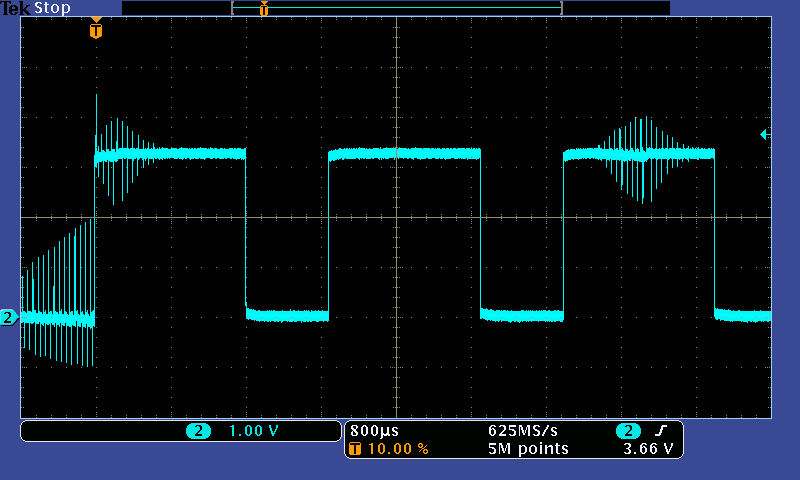
It is unsafe to fly without ground connected. This is because for every positive pulse (the ESC signal) there needs to be an adjacent ground return path for a clean signal shape.
The image below shows how noisy the signal becomes if GND is not connected.
# 전원 연결 / 광절연 ESC
If using an opto-isolated ESC that does not provide a BEC / power output, please ensure that the ESC does not need its +5V line powered for the opto-isolator.
See the first section of this page explains for other power connection considerations.
# 잘못된 최소치
Some ESCs need to see a special low value pulse before switching on (to protect users who have the throttle stick in the middle position on power-up).
PX4 sends a value of PWM_MAIN_DISARM pulse when the vehicle is disarmed, which silences the ESCs when they are disarmed and ensures that ESCs initialise correctly.
This value should be set correctly for the ESC (correct values vary between roughly 1200 and 900 us).
# 시간 초과
Some ESCs may time out (preventing motor activation) if they have not received a valid low pulse within a few seconds of power on.
PX4 flight stack sends the PWM_MAIN_DISARM pulse idle/disarmed pulse right after power on. Provided this is configured correctly, ESCs will not time out.
# 유효한 펄스 모양, 전압 및 업데이트 속도
Note
This should not be a problem, but is included for completeness
Pixhawk uses active high pulses, as used by all the major brands (Futaba, Spektrum, FrSky).
PWM interfaces are not formally standardised, however, the normal micro controllers all use TTL or CMOS voltage levels. TTL is defined as low < 0.8V and high > 2.0V with some manufacturers using > 2.4V for additional noise margin. CMOS logic is defined with similar voltage levels. 5V levels are never required to successfully switch to an on state.
TIP
Futaba, FrSky and Spektrum receivers output 3.3V or 3.0V voltage levels, as they are well above 2.4V. Pixhawk has adopted this common industry pattern and outputs 3.3V levels on recent boards.