# Omnibus F4 SD
WARNING
PX4 does not manufacture this (or any) autopilot. Contact the manufacturer for support or compliance issues.
The Omnibus F4 SD is a controller board designed for racers. In contrast to a typical racer board it has some additional features, such as an SD card and a faster CPU.

These are the main differences compared to a Pixracer:
- Lower price
- Fewer IO ports (though it's still possible to attach a GPS or a Flow sensor for example)
- Requires external pull up resistor on the I2C bus for external GPS, see I2C below.
- Less RAM (192 KB vs. 256 KB) and FLASH (1 MB vs. 2 MB)
- Same board dimensions as a Pixracer, but slightly smaller form factor (because it has less connectors)
- Integrated OSD (not yet implemented in software)
TIP
All the usual PX4 features can still be used for your racer!
Note
This flight controller is manufacturer supported.
# Key Features
- Main System-on-Chip: STM32F405RGT6 (opens new window)
- CPU: 168 MHz ARM Cortex M4 with single-precision FPU
- RAM: 192 KB SRAM
- FLASH: 1 MB
- Standard racer form factor: 36x36 mm with standard 30.5 mm hole pattern
- MPU6000 Accel / Gyro
- BMP280 Baro (not all boards have it mounted)
- microSD (for logging)
- Futaba S.BUS and S.BUS2 / Spektrum DSM2 and DSMX / Graupner SUMD / PPM input / Yuneec ST24
- OneShot PWM out (configurable)
- Built-in current sensor
- Built-in OSD chip (AB7456 via SPI)
# Where to Buy
The board is produced by different vendors, with some variations (e.g. with or without a barometer).
TIP
PX4 is compatible with boards that support the Betaflight OMNIBUSF4SD target (if OMNIBUSF4SD is present on the product page the board should work with PX4).
TIP
Any Omnibus F4 labeled derivative (e.g. clone) should work as well. However, power distribution on these boards is of varying quality.
These are the boards tested and known to work:
Hobbywing XRotor Flight Controller F4 (opens new window)
Note
This board fits on top of the Hobbywing XRotor Micro 40A 4in1 ESC (opens new window) without soldering. This ESC board also provides power for the Omnibus board.
Purchase from:
Original Airbot Omnibus F4 SD
Purchase from:
Accessories include:
- ESP8266 WiFi Module for MAVLink telemetry. You need to connect these pins: GND, RX, TX, VCC and CH-PD (CH-PD to 3.3V). The baud rate is 921600.
# Connectors
Boards from different vendors (based on this design) can have significantly different layout. Layouts/Silkscreens for various versions are shown below.
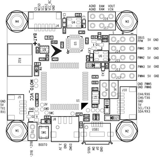
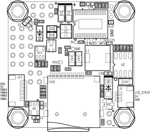
# Airbot Omnibus F4 SD
Below are silkscreens for the Airbot Omnibus F4 SD (V1), showing both top and bottom.
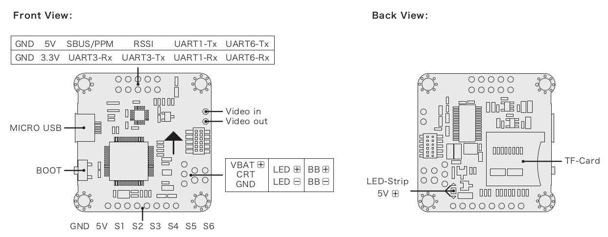
# Hobbywing XRotor Flight Controller F4
Below are silkscreens for the Hobbywing XRotor Flight Controller F4.
# Pinouts
# Radio Control
RC is connected to one of the following ports:
- UART1
- SBUS/PPM port (via inverter, internally goes to UART1)
Note
Some Omnibus F4 boards have a jumper connecting either or both the MCU SBUS and PPM to a single pin header. Set your jumper or solder bridge to the appropriate MCU pin before use.
# UARTs
UART6: GPS port
TX: MCU pin PC6
RX: MCU pin PC7
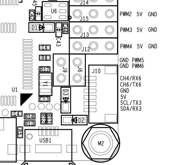
Airbot Omnibus F4 SD Pinout is on Port J10 (TX6/RX6):
UART4
- TX: MCU pin PA0
- RX: MCU pin PA1
- 57600 baud
- This can be configured as the
TELEM 2port. - Airbot Omnibus F4 SD Pinout:
- TX: RSSI pin
- RX: PWM out 5
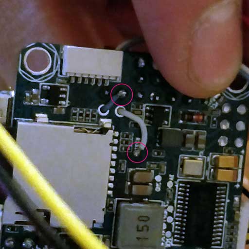
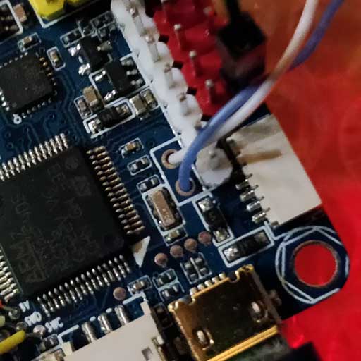
# I2C
There is one I2C port available via:
- SCL: MCU pin PB10 (might be labeled as TX3)
- SDA: MCU pin PB11 (might be labeled as RX3)
Note
You will need external pullups on both signals (clock and data). You can use 2.2k pullups for example to attach an external mag.
- Airbot Omnibus F4 SD Pinout is on Port J10 (SCL [clock] / SCA [data]):
Here is an example implementation. I used a Spektrum plug to get 3.3v from the DSM port, connecting only 3.3v + to each line via 2.2k resistor.

# Serial Port Mapping
| UART | Device | Port |
|---|---|---|
| USART1 | /dev/ttyS0 | SerialRX |
| USART4 | /dev/ttyS1 | TELEM1 |
| USART6 | /dev/ttyS2 | GPS |
# RC Telemetry
The Omnibus supports telemetry to the RC Transmitter using FrSky Telemetry or CRSF Crossfire Telemetry.
# CRSF Crossfire Telemetry
TBS CRSF Crossfire telemetry is used to send telemetry data from the flight controller (the vehicle's attitude, battery, flight mode and GPS data) to the RC transmitter (Taranis).
Benefits over FrSky telemetry include:
- Only a single UART is needed for RC and telemetry.
- The CRSF protocol is optimized for low latency.
- 150 Hz RC update rate.
- The signals are uninverted and thus no (external) inverter logic is required.
For Omnibus we recommend the TBS Crossfire Nano RX (opens new window), since it is specifically designed for small Quads.
On the handheld controller (e.g. Taranis) you will also need a Transmitter Module (opens new window). This can be plugged into the back of the RC controller.
Note
The referenced links above contains the documentation for the TX/RX modules.
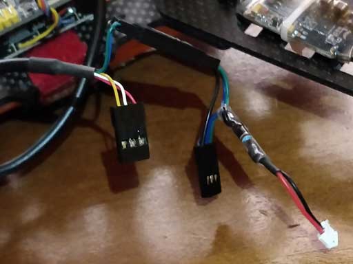
# Setup
Connect the Nano RX and Omnibus pins as shown:
| Omnibus UART1 | Nano RX |
|---|---|
| TX | Ch2 |
| RX | Ch1 |
Nothing else needs to be configured on PX4 flight controller side - the RC protocol is auto-detected.
Next update the TX/RX modules to use the CRSF protocol and set up telemetry. Instructions for this are provided in the TBS Crossfire Manual (opens new window) (search for 'Setting up radio for CRSF').
# Schematics
The schematics are provided by Airbot (opens new window): OmnibusF4-Pro-Sch.pdf (opens new window).
# PX4 Bootloader Update
The board comes pre-installed with Betaflight (opens new window). Before PX4 firmware can be installed, the PX4 bootloader must be flashed. Download the omnibusf4sd_bl.hex (opens new window) bootloader binary and read this page for flashing instructions.
# Building Firmware
To build PX4 for this target:
make omnibus_f4sd_default
# Installing PX4 Firmware
The firmware can be installed in any of the normal ways:
- Build and upload the source
make omnibus_f4sd_default upload - Load the firmware using QGroundControl. You can use either pre-built firmware or your own custom firmware.
# Configuration
In addition to the basic configuration, the following parameters are important:
| Parameter | Setting |
|---|---|
| SYS_HAS_MAG | This should be disabled since the board does not have an internal mag. You can enable it if you attach an external mag. |
| SYS_HAS_BARO | Disable this if your board does not have a barometer. |
| MOT_ORDERING | If you use a 4-in-1 ESC with Betaflight/Cleanflight motor assignment, this parameter can be set accordingly. |
# Further Info
A review with further information of the board can be found here (opens new window).
This page (opens new window) also provides a nice overview with pinouts and setup instructions.