# CUAV V5 nano Autopilot
WARNING
PX4 does not manufacture this (or any) autopilot. Contact the manufacturer (opens new window) for hardware support or compliance issues.
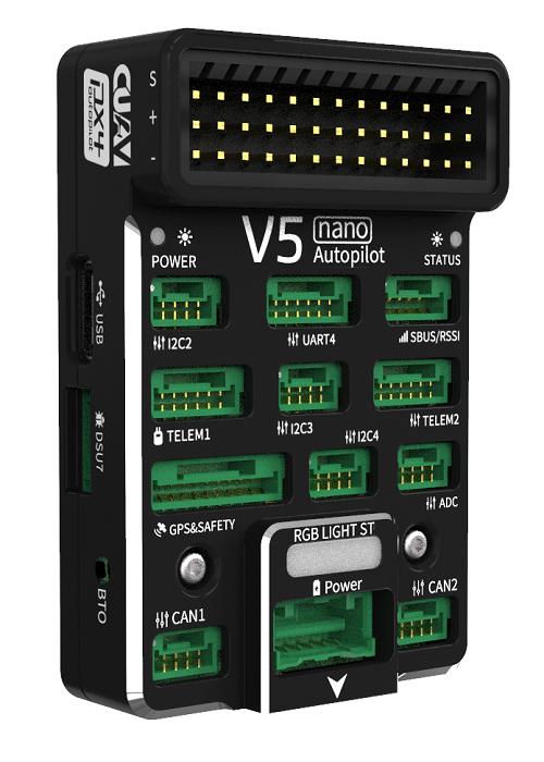
V5 nano® is an autopilot for space-constrained applications, designed by CUAV® in collaboration with the PX4 team.
The autopilot is small enough to use in 220mm racing drones, but remains powerful enough for most drone use.
Note
The V5 nano is similar to the CUAV V5+, but has an all-in-one form factor, fewer PWM ports (can't be used for airframes that use AUX ports), and does not have internal damping.
Some of its main features include:
- Full compatibility with the Pixhawk project (opens new window) FMUv5 design standard and uses the Pixhawk Connector Standard (opens new window) for all external interfaces.
- More advanced processor, RAM and flash memory than FMU v3, along with more stable and reliable sensors.
- Firmware-compatible with PX4.
- Generous 2.6mm spacing for I/O pins, making it easier to use all the interfaces.
Note
This flight controller is manufacturer supported.
# Quick Summary
Main FMU Processor: STM32F765◦32 Bit Arm® Cortex®-M7, 216MHz, 2MB memory, 512KB RAM
On-board sensors:
- Accel/Gyro: ICM-20689
- Accel/Gyro: ICM-20602
- Accel/Gyro: BMI055
- Magnetometer: IST8310
- Barometer: MS5611
Interfaces: 8 PWM outputs
- 3 dedicated PWM/Capture inputs on FMU
- Dedicated R/C input for CPPM
- Dedicated R/C input for Spektrum / DSM and S.Bus
- Analog / PWM RSSI input
- 4 general purpose serial ports
- 3 I2C ports
- 4 SPI buses
- 2 CAN Buses
- Analog inputs for voltage / current of battery
- 2 additional analog inputs
- Supports nARMED
Power System: Power Brick Input: 4.75~5.5V
USB Power Input: 4.75~5.25V
Weight and Dimensions:
- Dimensions: 60*40*14mm
Other Characteristics:
- Operating temperature: -20 ~ 85°C (Measured value)
# Purchase
CUAV Aliexpress (opens new window) (international users)
CUAV Taobao (opens new window) (China Mainland users)
Note
Autopilot may be purchased with included Neo GPS module
# Connections (Wiring)
# Pinouts
Download V5 nano pinouts from here (opens new window).
# Building Firmware
TIP
Most users will not need to build this firmware! It is pre-built and automatically installed by QGroundControl when appropriate hardware is connected.
To build PX4 for this target:
make px4_fmu-v5_default
# Debug Port
The PX4 System Console and SWD interface operate on the FMU Debug port (DSU7).
The board does not have an I/O debug interface.
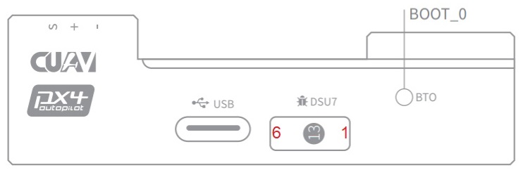
The debug port (DSU7) uses a JST BM06B (opens new window) connector and has the following pinout:
| Pin | Signal | Volt |
|---|---|---|
| 1 (red) | 5V+ | +5V |
| 2 (blk) | DEBUG TX (OUT) | +3.3V |
| 3 (blk) | DEBUG RX (IN) | +3.3V |
| 4 (blk) | FMU_SWDIO | +3.3V |
| 5 (blk) | FMU_SWCLK | +3.3V |
| 6 (blk) | GND | GND |
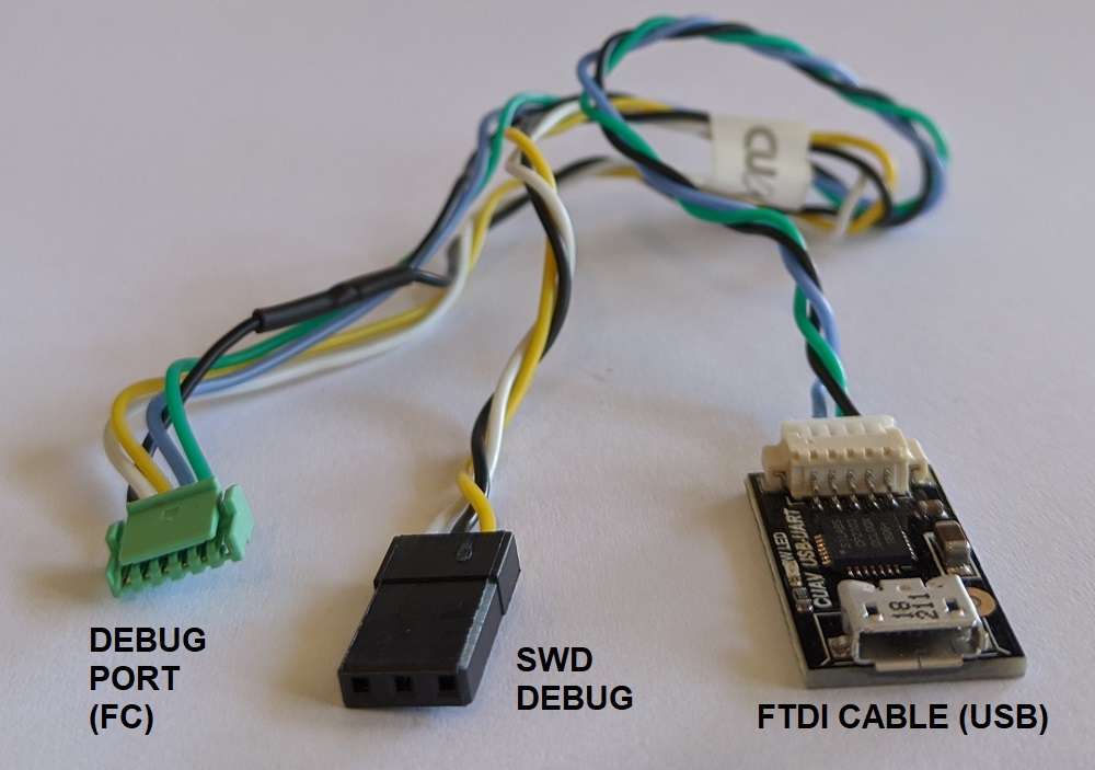
The product package includes a convenient debug cable that can be connected to the DSU7 port.
This splits out an FTDI cable for connecting the PX4 System Console to a computer USB port, and SWD pins used for SWD/JTAG debugging.
The provided debug cable does not connect to the SWD port Vref pin (1).
WARNING
The SWD Vref pin (1) uses 5V as Vref but the CPU is run at 3.3V!
Some JTAG adapters (SEGGER J-Link) will use the Vref voltage to set the voltage on the SWD lines.
For direct connection to Segger Jlink we recommended you use the 3.3 Volts from pin 4 of the connector marked DSM/SBUS/RSSI to provide Vtref to the JTAG (i.e. providing 3.3V and NOT 5V).
For more information see Using JTAG for hardware debugging.
# Serial Port Mapping
| UART | Device | Port |
|---|---|---|
| UART1 | /dev/ttyS0 | GPS |
| USART2 | /dev/ttyS1 | TELEM1 (flow control) |
| USART3 | /dev/ttyS2 | TELEM2 (flow control) |
| UART4 | /dev/ttyS3 | TELEM4 |
| USART6 | /dev/ttyS4 | TX is RC input from SBUS_RC connector |
| UART7 | /dev/ttyS5 | Debug Console |
| UART8 | /dev/ttyS6 | Not connected (no PX4IO) |
# Voltage Ratings
V5 nano must be powered from the Power connector during flight, and may also/alternatively be powered from USB for bench testing.
Note
The PM2 connector cannot not be used for powering the V5 nano (see this issue).
Note
The Servo Power Rail is neither powered by, nor provides power to the FMU. However, the pins marked + are all common, and a BEC may be connected to any of the servo pin sets to power the servo power rail.
# Over Current Protection
The V5 nano has no over current protection.
# Peripherals
- Digital Airspeed Sensor (opens new window)
- Telemetry Radio Modules (opens new window)
- Rangefinders/Distance sensors
# Supported Platforms / Airframes
Any multicopter / airplane / rover or boat that can be controlled with normal RC servos or Futaba S-Bus servos. The complete set of supported configurations can be seen in the Airframes Reference.
# Compatibility
CUAV adopts some differentiated designs and is incompatible with some hardware, which will be described below.
# Neo v2.0 GPS not compatible with other devices
The Neo v2.0 GPS that is recommended for use with CUAV V5+ and CUAV V5 nano is not fully compatible with other Pixhawk flight controllers (specifically, the buzzer part is not compatible and there may be issues with the safety switch).
The UAVCAN NEO V2 PRO GNSS receiver (opens new window) can also be used, and is compatible with other flight controllers.
# Using JTAG for hardware debugging
DSU7 FMU Debug Pin 1 is 5 volts - not the 3.3 volts of the CPU.
Some JTAG probes use this voltage to set the IO levels when communicating to the target.
For direct connection to Segger Jlink we recommended you use the 3.3 Volts of DSM/SBUS/RSSI pin 4 as Pin 1 on the debug connector (Vtref).
# PM2 cannot power the flight controller
PM2 can only measure battery voltage and current, but not power the flight controller.
WARNING
PX4 does not support this interface.
# Known Issues
The issues below refer to the batch number in which they first appear. The batch number is the four-digit production date behind V01 and is displayed on a sticker on the side of the flight controller. For example, the serial number Batch V011904((V01 is the number of V5, 1904 is the production date, that is, the batch number).
# SBUS / DSM / RSSI interface Pin1 unfused
WARNING
This is a safety issue.
Please do not connect other equipment (except RC receiver) on SBUS / DSM / RSSI interface - this can lead to equipment damage!
- Found: Batches V01190904xxxx
- Fixed: Batches later than V01190904xxxx