# ECL EKF 사용
이 섹션은 ECL EKF 알고리즘에 관한 질문에 대한 답변들입니다.
Extract the .ulg log file using, for example, QGroundControl: Analyze > Log Download (opens new window) :::note The same log file can be used to tune the multirotor wind estimator.
:::
# ECL EKF는 무엇입니까?
ECL(Estimation and Control Library)은 EKF(Extended Kalman Filter) 알고리즘으로 센서 측정 데이터를 처리하여 상태의 추정치를 제공합니다.
- 북쪽, 동쪽, 아래쪽 지역 지구 프레임에서 X, Y, Z 본체의 회전을 정의하는 쿼터니언
- IMU의 속도 - 북쪽, 동쪽, 아래쪽 (m/s)
- IMU에서의 위치 - 북쪽, 동쪽, 아래쪽 (m)
- IMU 델타 각도 편향 추정값 - X, Y, Z (rad)
- IMU 델타 속도 바이어스 추정값 - X, Y, Z (m/s)
- 지구 자기장 요소 - 북쪽, 동쪽, 아래쪽 (gauss)
- 기체 프레임 자기장 바이어스 - X,Y,Z (gauss)
- 풍속 - 북쪽, 동쪽 (m/s)
EKF는 IMU와 관련된 각 측정에서 다른 시간 지연을 허용하기 위하여, 지연된 '융합 시간 지평'에서 실행됩니다. 각 센서의 데이터는 FIFO 버퍼링되고, EKF에 의해 버퍼에서 검색되어 적절한 시간에 사용됩니다. 각 센서에 대한 지연 보상은 EKF2 _*_DELAY 매개변수로 제어합니다.
보완 필터는 버퍼링 된 IMU 데이터를 사용하여 '퓨전 시간 수평선'에서 현재 시간으로 상태를 전달하는 데 사용됩니다. 이 필터의 시간 상수는 EKF2_TAU_VEL 및 EKF2_TAU_POS 매개변수로 제어합니다.
Note
'퓨전 시간 지평'지연 및 버퍼 길이는 EKF2_*_DELAY 매개변수 중 가장 큰 매개변수로 결정합니다. 센서를 사용하지 않는 경우에는 시간 지연을 0으로 설정하는 것이 좋습니다. '퓨전 시간 지평' 지연을 줄이면 상태를 현재 시간으로 전달하는 데 사용되는 보완 필터의 오류가 줄어 듭니다.
위치와 속도 상태는 제어 루프로 출력되기 전에 IMU와 본체 프레임 간의 오프셋을 고려하여 조정됩니다. 본체 프레임에 상대적인 IMU의 위치는 EKF2_IMU_POS_X, Y, Z 매개변수로 설정합니다.
EKF는 상태 예측에만 IMU 데이터를 사용합니다. IMU 데이터는 EKF 유도에서 관측치로 사용되지 않습니다. 공분산 예측, 상태 업데이트와 공분산 업데이트에 대한 대수 방정식은 Matlab 기호 도구 상자를 사용하여 파생되었으며, Matlab 기호 파생 (opens new window)를 참고하십시오.
# 단일 EKF 인스턴스 실행
기본 동작은 EKF의 단일 인스턴스를 실행하는 것입니다. 이 경우 센서 선택 및 페일 오버는 EKF에서 데이터를 수신하기 전에 수행됩니다. 이는 데이터 손실과 같은 제한된 수의 센서 오류에 대한 보호를 제공하지만, EKF 및 제어 루프의 보상 능력을 초과하는 부정확한 데이터를 제공하는 센서에 대해서는 보호하지 않습니다.
단일 EKF 인스턴스를 실행하기위한 매개 변수는 다음과 같습니다.
- EKF2_MULTI_IMU = 0
- EKF2_MULTI_MAG = 0
- SENS_IMU_MODE = 1
- SENS_MAG_MODE = 1
# 다중 EKF 인스턴스 실행
IMU와 자력계의 갯수와 자동조종장치의 CPU 용량에 따라 EKF 다중 인스턴스를 실행이 가능합니다. 이는 광범위한 센서 오류에 대한 보호를 제공하며, 서로 다른 센서 조합을 사용하는 EKF 인스턴스에서 달성됩니다. EKF 인스턴스의 내부 일관성을 비교함으로써 EKF 선택기는 최상의 데이터 일관성으로 EKF와 센서 조합을 결정할 수 있습니다. 이를 통하여 IMU 바이어스의 갑작스런 변화, 포화 또는 고착된 데이터 등과 같은 오류를 감지하고 격리할 수 있습니다.
총 EKF 인스턴스 수는 EKF2_MULTI_IMU 및 EKF2_MULTI_MAG에서 선택한 IMU 수와 자력계 수의 곱이며 공식은 다음과 같습니다.
N_instances = MAX(EKF2_MULTI_IMU , 1) x MAX(EKF2_MULTI_MAG , 1)
예를 들어, 2 개의 IMU와 2 개의 자력계가 있는 자동조종장치는 각 인스턴스가 다음 센서 조합을 사용하는 총 4 개의 EKF 인스턴스에 대해 EKF2_MULTI_IMU = 2와 EKF2_MULTI_MAG = 2로 실행할 수 있습니다.
- EKF 인스턴스 1 : IMU 1, 자력계 1
- EKF 인스턴스 2 : IMU 1, 자력계 2
- EKF 인스턴스 3 : IMU 2, 자력계 1
- EKF 인스턴스 4 : IMU 2, 자력계 2
처리 가능한 IMU 또는 자력계 센서의 최대 갯수는 이론상 최대 4 x 4 = 16 EKF 인스턴스에 대해 각각 4 개입니다. 실제적으로는, 사용 가능한 컴퓨팅 리소스에 의해 제한됩니다. 이 기능을 개발하는 동안 STM32F7 CPU 기반 HW를 사용한 테스트에서 허용 가능한 처리로드 및 메모리 사용률을 가진 4 개의 EKF 인스턴스가 입증되었습니다.
WARNING
비행 전에 CPU 및 메모리 사용률을 확인하기위한 지상 기반 테스트를 수행하여야 합니다.
EKF2_MULTI_IMU> = 3이면 EKF 선택기가 결함이있는 IMU를 더 빠르게 격리하기 위해 중앙값 선택 전략을 적용 할 수 있기 때문에, 큰 속도의 자이로 오류에 대한 장애 조치 시간이 더욱 단축됩니다.
다중 EKF 인스턴스에 대한 설정은 다음 매개변수로 제어됩니다.
SENS_IMU_MODE : IMU 센서 다양성 (예 : EKF2_MULTI_IMU > 1)으로 다중 EKF 인스턴스를 실행하는 경우 0으로 설정합니다.
1 (단일 EKF 작동의 기본값)로 설정하면 센서 모듈이 EKF에서 사용하는 IMU 데이터를 선택합니다. 이것은 센서의 데이터 손실에 대한 보호 기능를 제공하지만, 잘못된 센서 데이터에 대해서는 보호하지 않습니다. 0으로 설정하면 센서 모듈이 선택하지 않습니다.
SENS_MAG_MODE : 자력계 센서 다양성 (예 : EKF2_MULTI_MAG > 1)으로 다중 EKF 인스턴스를 실행하는 경우 0으로 설정합니다.
1 (단일 EKF 작동의 기본값)로 설정하면 센서 모듈이 EKF에서 사용하는 자력계 데이터를 선택합니다. 이것은 센서의 데이터 손실에 대한 보호 기능를 제공하지만, 잘못된 센서 데이터에 대해서는 보호하지 않습니다. 0으로 설정하면 센서 모듈이 선택하지 않습니다.
EKF2_MULTI_IMU : 이 매개변수는 다중 EKF에서 사용하는 IMU 센서의 수를 지정합니다.
EKF2_MULTI_IMU<= 1이면 첫 번째 IMU 센서만 사용됩니다. SENS_IMU_MODE = 1이면 센서 모듈에서 선택한 센서가됩니다.EKF2_MULTI_IMU> = 2이면 지정된 수의 IMU 센서에 대해 최대 4 개 또는 존재하는 IMU 수까지 별도의 EKF 인스턴스가 실행됩니다.EKF2_MULTI_MAG : 이 매개변수는 다중 EKF에서 사용하는 자력계 센서의 수를 지정합니다.
EKF2_MULTI_MAG<= 1이면 첫 번째 자력계 센서만 사용됩니다. SENS_MAG_MODE = 1이면 센서 모듈에서 선택한 센서가 사용됩니다.EKF2_MULTI_MAG> = 2이면 별도의 EKF 인스턴스가 지정된 수의 자력계 센서에 대해 최대 4 개 또는 존재하는 자력계의 수보다 작은 수에 대하여 실행됩니다.
Note
다중 EKF 인스턴스 비행 로그의 EKF2 재생은 지원되지 않습니다. EKF 재생을 위해 녹화를 활성화하려면 단일 EKF 인스턴스를 활성화하도록 매개변수를 설정하여야 합니다.
# EKF는 어떤 센서 측정값을 사용하나요?
EKF에는 다양한 센서 측정 조합으로 작동하는 여러가지 모드가 있습니다. 시작시 필터는 센서의 최소 가능한 조합을 확인하고 초기 기울기, 편 요각 및 높이 정렬이 완료된 후 회전, 수직 속도, 수직 위치, IMU 델타 각도 바이어스 및 IMU 델타 속도 바이어스 추정치를 제공하는 모드로 들어갑니다.
이 모드에는 IMU 데이터, 요(자기계 또는 외부 비전) 소스와 고도 데이터 소스가 필요합니다. 이 최소 데이터 세트는 모든 EKF 모드에 필요합니다. 그런 다음 다른 센서 데이터를 사용하여 추가 상태를 추정할 수 있습니다.
# 관성계
- 3축 본체 고정 관성 측정 장치 델타 각도와 최소 속도 100Hz의 델타 속도 데이터. Note: 원뿔 보정은 EKF에서 사용하기 전에 IMU 델타 각도 데이터에 적용되어야 합니다.
# 자력계
최소 5Hz 속도의 3축 본체 고정 자력계 데이터 (또는 외부 비전 시스템 포즈 데이터)가 필요합니다. 자력계 데이터는 두 가지 방법으로 사용할 수 있습니다.
- 자력계는 기울기 추정과 자기 편각을 사용하여 요 각도를 측정합니다. 이 요 각도는 EKF에서 관찰로 사용됩니다. 이 방법은 정확도가 떨어지고, 본체 필드 오프셋의 학습을 허용하지 않지만, 자기 이상과 대규모 스타트업 자이로 바이어스에 더 강력합니다. 지상에서 시동에 사용되는 기본 방법입니다.
- XYZ 자력계 판독 값은 별도의 관측치로 사용됩니다. 이 방법은 더 정확하고 본체 프레임 오프셋을 학습할 수 있지만, 지구 자기장 환경이 느리게 변하고 심각한 외부 자기 이상이있을 때 성능이 저하된다고 가정합니다.
이러한 모드를 선택하는 데 사용되는 로직은 EKF2_MAG_TYPE 매개변수로 설정됩니다.
이 옵션은 이중 안테나 GPS에서 yaw를 사용하여 교체하거나 IMU와 GPS 속도 데이터를 사용하여 차량 움직임에서 요를 추정하여 자력계 없이 작동할 수 있습니다.
# 고도
고도 데이터 소스 - GPS, 기압, 거리 측정기 또는 최소 5Hz 속도의 외부 비전이 필요합니다.
Note
높이 데이터의 기본 소스는 EKF2_HGT_MODE 매개변수에 의해 제어됩니다.
이러한 측정 값이 없으면, EKF가 시작되지 않습니다. 이러한 측정이 감지되면, EKF는 상태를 초기화하고 틸트와 요 정렬을 완료합니다. 틸트와 요 정렬이 완료되면 EKF는 추가 센서 데이터를 사용할 수 있는 모드로 전환할 수 있습니다.
# 정압 위치 오차 보정
기압 고도는 차량 풍속과 방향으로 인한 공기 역학적 장애로 인해 발생하는 오류가 존재합니다. 기압 고도는 차량 풍속과 방향으로 인한 공기 역학적 장애로 인해 발생하는 오류가 존재합니다. ECL/EKF2 추정기 라이브러리를 사용하는 EKF2 모듈은 풍속 상태 추정이 활성화된 경우, 오류 보상 방법을 제공합니다.
고정익에서 작동하는 플랫폼의 경우 풍속 상태 추정에는 대기속도 또는 Synthetic Sideslip 융합이 활성화되어 있어야 합니다.
멀티콥터의 경우 Drag Specific Forces의 융합을 활성화하고 조정하여 필요한 풍속 상태 추정치를 제공할 수 있습니다.
The EKF2 module models the error as a body fixed ellipsoid that specifies the fraction of dynamic pressure that is added to/subtracted from the barometric pressure - before it is converted to a height estimate.
A good tuning is obtained as follows:
- Fly once in Position mode repeatedly forwards/backwards/left/right/up/down between rest and maximum speed (best results are obtained when this testing is conducted in still conditions).
- Extract the .ulg log file using, for example, QGroundControl: Analyze > Log Download (opens new window) :::note The same .ulg log file can also be used to tune the static pressure position error coefficients. :::
- Use the log with the baro_static_pressure_compensation_tuning.py (opens new window) Python script to obtain the optimal set of parameters.
Tuning parameters:
# Barometer bias compensation
A barometer at a constant altitude is subject to drift in its measurements due to changes in the ambient pressure environment or variations of the sensor temperature. To compensate for this measurement error, EKF2 estimates the bias using GNSS height (if available) a "non drifting" reference. No tuning is required.
# GPS
# 위치 및 속도 측정
GPS measurements will be used for position and velocity if the following conditions are met:
- GPS 사용은 EKF2_AID_MASK 매개변수로 활성화됩니다.
- GPS 품질 검사를 통과하였습니다. 이 검사는 EKF2_GPS_CHECK 및
EKF2_REQ _*매개변수에 의해 제어됩니다. - GPS 고도는 EKF2_HGT_MODE 매개변수 설정을 통해 EKF에서 직접 사용할 수 있습니다.
# 방향(Yaw) 측정
Some GPS receivers such as the Trimble MB-Two RTK GPS receiver (opens new window) can be used to provide a heading measurement that replaces the use of magnetometer data. This can be a significant advantage when operating in an environment where large magnetic anomalies are present, or at latitudes here the earth's magnetic field has a high inclination. Use of GPS yaw measurements is enabled by setting bit position 7 to 1 (adding 128) in the EKF2_AID_MASK parameter.
# GPS 방향 측정
The EKF runs an additional multi-hypothesis filter internally that uses multiple 3-state Extended Kalman Filters (EKF's) whose states are NE velocity and yaw angle. These individual yaw angle estimates are then combined using a Gaussian Sum Filter (GSF). The individual 3-state EKF's use IMU and GPS horizontal velocity data (plus optional airspeed data) and do not rely on any prior knowledge of the yaw angle or magnetometer measurements. This provides a backup to the yaw from the main filter and is used to reset the yaw for the main 24-state EKF when a post-takeoff loss of navigation indicates that the yaw estimate from the magnetometer is bad. This will result in an Emergency yaw reset - magnetometer use stopped message information message at the GCS.
Data from this estimator is logged when ekf2 replay logging is enabled and can be viewed in the yaw_estimator_status message. The individual yaw estimates from the individual 3-state EKF yaw estimators are in the yaw fields. The GSF combined yaw estimate is in the yaw_composite field. The variance for the GSF yaw estimate is in the yaw_variance field. All angles are in radians. Weightings applied by the GSF to the individual 3-state EKF outputs are in theweight fields.
This also makes it possible to operate without any magnetometer data or dual antenna GPS receiver for yaw provided some horizontal movement after takeoff can be performed to enable the yaw to become observable. To use this feature, set EKF2_MAG_TYPE to none (5) to disable magnetometer use. Once the vehicle has performed sufficient horizontal movement to make the yaw observable, the main 24-state EKF will align it's yaw to the GSF estimate and commence use of GPS.
# 이중 수신기
Data from GPS receivers can be blended using an algorithm that weights data based on reported accuracy (this works best if both receivers output data at the same rate and use the same accuracy). The mechanism also provides automatic failover if data from a receiver is lost (it allows, for example, a standard GPS to be used as a backup to a more accurate RTK receiver). This is controlled by the SENS_GPS_MASK parameter.
The SENS_GPS_MASK parameter is set by default to disable blending and always use the first receiver, so it will have to be set to select which receiver accuracy metrics are used to decide how much each receiver output contributes to the blended solution. Where different receiver models are used, it is important that the SENS_GPS_MASK parameter is set to a value that uses accuracy metrics that are supported by both receivers. For example do not set bit position 0 to true unless the drivers for both receivers publish values in the s_variance_m_s field of the vehicle_gps_position message that are comparable. This can be difficult with receivers from different manufacturers due to the different way that accuracy is defined, e.g. CEP vs 1-sigma, etc.
The following items should be checked during setup:
- 두 번째 수신기의 데이터가 있는 지 확인합니다. 이는
vehicle_gps_position_1으로 기록되며listener vehicle_gps_position -i 1명령을 사용하여 nsh 콘솔을 통해 연결되었을 때 확인할 수 있습니다. GPS_2_CONFIG 매개변수를 올바르게 설정하여야 합니다. - 각 수신기에서
s_variance_m_s,eph및epv데이터를 확인하고 사용할 수있는 정확도 메트릭을 결정합니다. If both receivers output sensibles_variance_m_sandephdata, and GPS vertical position is not being used directly for navigation, then setting SENS_GPS_MASK to 3 is recommended. Where onlyephdata is available and both receivers do not outputs_variance_m_sdata, set SENS_GPS_MASK to 2. 비트 위치 2는 GPS가 EKF2_HGT_MODE 매개변수를 사용하여 기본 고도 소스로 선택되었고 두 수신기 모두 합리적인epv데이터를 출력하는 경우에만 설정됩니다. - 혼합 수신기 데이터의 출력은
ekf_gps_position으로 기록되며,listener ekf_gps_position명령을 사용하여 nsh 터미널을 연결하여 확인할 수 있습니다. - 수신기가 다른 속도로 출력하는 경우에는 혼합 출력은 더 느린 수신기의 속도로 결정됩니다. 가능한 경우 수신기는 동일한 속도로 출력하도록 설정하는 것이 바람직합니다.
# GNSS 성능 요구 사항
For the ECL to accept GNSS data for navigation, certain minimum requirements need to be satisfied over a period of time, defined by EKF2_REQ_GPS_H (10 seconds by default).
Minima are defined in the EKF2_REQ_* parameters and each check can be en-/disabled using the EKF2_GPS_CHECK parameter.
The table below shows the different metrics directly reported or calculated from the GNSS data, and the minimum required values for the data to be used by ECL. In addition, the Average Value column shows typical values that might reasonably be obtained from a standard GNSS module (e.g. u-blox M8 series) - i.e. values that are considered good/acceptable.
| 메트릭 | 최소 요구 사항 | 평균 | 단위 | 참고 |
|---|---|---|---|---|
| eph | < 3 (EKF2_REQ_EPH) | 0.8 | 미터 | 수평 위치의 표준 편차 |
| epv | < 5 (EKF2_REQ_EPV) | 1.5 | 미터 | 수직 위치의 표준 편차 |
| 위성 개수 | ≥6 (EKF2_REQ_NSATS) | 14 | - | |
| sacc | < 0.5 (EKF2_REQ_SACC) | 0.2 | m/s | 수평 속도의 표준 편차 |
| fix type | ≥ 3 | 4 | - | 0-1: 수정 없음, 2: 2D 수정, 3: 3D 수정, 4: RTCM 차등 코드, 5: Real-Time Kinematic, float, 6: Real-Time Kinematic, 고정, 8: 외삽 |
| PDOP | < 2.5 (EKF2_REQ_PDOP) | 1.0 | - | 정밀도의 위치 희석 |
| hpos drift rate | < 0.1 (EKF2_REQ_HDRIFT) | 0.01 | m/s | 보고된 GNSS 위치에서 계산된 드리프트 율 (정지시). |
| vpos drift rate | < 0.2 (EKF2_REQ_VDRIFT) | 0.02 | m/s | 보고된 GNSS 고도에서 계산된 드리프트 율 (정지시). |
| hspd | < 0.1 (EKF2_REQ_HDRIFT) | 0.01 | m/s | 보고된 GNSS 수평 속도의 필터링 크기. |
| vspd | < 0.2 (EKF2_REQ_VDRIFT) | 0.02 | m/s | 보고된 GNSS 수직 속도의 필터링 크기. |
Note
The hpos_drift_rate, vpos_drift_rate and hspd are calculated over a period of 10 seconds and published in the ekf2_gps_drift topic. Note that ekf2_gps_drift is not logged!
# 거리 측정기
Range finder distance to ground is used by a single state filter to estimate the vertical position of the terrain relative to the height datum.
If operating over a flat surface that can be used as a zero height datum, the range finder data can also be used directly by the EKF to estimate height by setting the EKF2_HGT_MODE parameter to 2.
# Range Finder Obstruction Detection
The EKF can detect whether the rangefinder path-to-ground is obstructed (perhaps by a payload) using a kinematic consistency check between the vertical velocity estimate and the numerical derivative of the range finder data. If the range finder is statistically inconsistent with EKF2, the sensor is rejected for the rest of the flight unless the statistical test passes again for at least 1 second at a vertical speed of 0.5m/s or more.
The check is only enabled when the rangefinder is not used as the primary height source, and is only active while the vehicle is not moving horizontally (as it assumes a static ground height).
For effective obstruction detection, the range finder noise parameter needs to be tightly tuned using flight data. The kinematic consistency gate parameter can then be adjusted to obtain the desired fault detection sensitivity.
Tuning parameters:
# 대기속도
Equivalent Airspeed (EAS) data can be used to estimate wind velocity and reduce drift when GPS is lost by setting EKF2_ARSP_THR to a positive value. Airspeed data will be used when it exceeds the threshold set by a positive value for EKF2_ARSP_THR and the vehicle type is not rotary wing.
# 합성 사이드슬립
Fixed wing platforms can take advantage of an assumed sideslip observation of zero to improve wind speed estimation and also enable wind speed estimation without an airspeed sensor. This is enabled by setting the EKF2_FUSE_BETA parameter to 1.
# 항력을 사용한 멀티콥터 바람 추정
Multi-rotor platforms can take advantage of the relationship between airspeed and drag force along the X and Y body axes to estimate North/East components of wind velocity. This is enabled by setting bit position 5 in the EKF2_AID_MASK parameter to true.
The relationship between airspeed and specific force (IMU accelerometer measurements) along the X and Y body axes is controlled by the EKF2_BCOEF_X, EKF2_BCOEF_Y and EKF2_MCOEF parameters which set the ballistic coefficients for flight in the X and Y directions, and the momentum drag produced by the propellers, respectively. The amount of specific force observation noise is set by the EKF2_DRAG_NOISE parameter.
A good tuning is obtained as follows:
- Fly once in Position mode repeatedly forwards/backwards/left/right/up/down between rest and maximum speed (best results are obtained when this testing is conducted in still conditions).
높이 데이터의 기본 소스는 [EKF2_HGT_MODE](../advanced_config/parameter_reference.md#EKF2_HGT_MODE) 매개변수에 의해 제어됩니다.
::: 3. Use the log with the mc_wind_estimator_tuning.py (opens new window) Python script to obtain the optimal set of parameters.
# 광류
Optical flow data will be used if the following conditions are met:
- 유효한 거리 센서 데이터를 사용할 수 있습니다.
- EKF2_AID_MASK 매개변수의 비트 위치 1이 참입니다.
- 유량 센서가 반환하는 품질 메트릭이 EKF2_OF_QMIN 매개변수로 설정된 최소 요구 사항보다 큽니다.
# 외부 비전 시스템
Position, velocity or orientation measurements from an external vision system, e.g. Vicon, can be used:
- EKF2_AID_MASK 매개변수의 비트 위치 3이 참이면 외부 비전 시스템의 수평 위치 데이터가 사용됩니다.
- EKF2_HGT_MODE 매개변수가 3으로 설정된 경우 외부 비전 시스템의 수직 위치 데이터가 사용됩니다.
- EKF2_AID_MASK 매개변수의 비트 위치 8이 참이면 외부 비전 시스템의 속도 데이터가 사용됩니다.
- EKF2_AID_MASK 매개변수의 비트 위치 4가 참인 경우 외부 비전 시스템의 방향 데이터가 요 추정에 사용됩니다.
- EKF2_AID_MASK 매개변수의 비트 위치 6이 참인 경우 외부 비전 참조 프레임 오프셋이 추정되고 외부 비전 시스템 데이터를 회전하는 데 사용됩니다.
Either bit 4 (EV_YAW) or bit 6 (EV_ROTATE) should be set to true, but not both together. Following EKF2_AID_MASK values are supported when using with an external vision system.
| EKF_AID_MASK 값 | 비트 설정 | 설명 |
|---|---|---|
| 321 | GPS + EV_VEL + ROTATE_EV | Heading w.r.t. North (추천) |
| 73 | GPS + EV_POS + ROTATE_EV | Heading w.r.t. North (비추천, 대신 EV_VEL을 추천함) |
| 24 | EV_POS + EV_YAW | Heading w.r.t. 외부 비전 프레임 |
| 72 | EV_POS + ROTATE_EV | Heading w.r.t. North |
| 272 | EV_VEL + EV_YAW | Heading w.r.t. 외부 비전 프레임 |
| 320 | EV_VEL + ROTATE_EV | Heading w.r.t. North |
| 280 | EV_POS + EV_VEL + EV_YAW | Heading w.r.t. 외부 비전 프레임 |
| 328 | EV_POS + EV_VEL + ROTATE_EV | Heading w.r.t. North |
The EKF considers uncertainty in the visual pose estimate. This uncertainty information can be sent via the covariance fields in the MAVLink ODOMETRY (opens new window) message or it can be set through the parameters EKF2_EVP_NOISE, EKF2_EVV_NOISE and EKF2_EVA_NOISE. You can choose the source of the uncertainty with EKF2_EV_NOISE_MD.
# ECL 라이브러리 EKF를 어떻게 사용합니까?
Set the SYS_MC_EST_GROUP parameter to 2 to use the ecl EKF.
# 다른 추정치들과 비교하여 ecl EKF의 장단점은 무엇입니까?
Like all estimators, much of the performance comes from the tuning to match sensor characteristics. Tuning is a compromise between accuracy and robustness and although we have attempted to provide a tune that meets the needs of most users, there will be applications where tuning changes are required.
For this reason, no claims for accuracy relative to the legacy combination of attitude_estimator_q + local_position_estimator have been made and the best choice of estimator will depend on the application and tuning.
# 단점
- ecl EKF는 확장칼만필터에 대한 이해와 탐색 문제를 적용한 튜닝이 필요한복잡한 알고리즘입니다. 따라서, 좋은 결과를 얻지 못한 사용자는 무엇을 변경해야하는지 파악하는 것이 더 어렵습니다.
- ecl EKF는 더 많은 RAM과 플래시 공간을 사용합니다.
- ecl EKF는 더 많은 로깅 공간을 사용합니다.
# 장점
- ecl EKF는 시간 지연 매개변수가 올바르게 설정되면 동적 조작 중에 정확도를 향상을 위하여 서로 다른 시간 지연 및 데이터 속도를 가진 센서의 데이터를 융합할 수 있습니다.
- ecl EKF는 다양한 유형의 센서들을 융합할 수 있습니다.
- ecl EKF는 센서 데이터에서 통계적으로 중요한 불일치를 감지하여 센서의 오류를 진단합니다.
- 고정익의 경우 ecl EKF는 대기 속도 센서를 사용하거나 사용하지 않고 풍속을 추정하고, 비행 중 GPS가 손실된 경우 사용할 수있는 데드 레커닝 시간을 연장하기 위하여 대기속도 측정 및 사이드 슬립 가정과 함께 풍속을 예측할 수 있습니다.
- ecl EKF는 비행 단계 사이에 큰 자세 변화를 경험하는 테일시터 및 기타 기체의 정확도를 향상시키는 3축 가속도계 바이어스를 추정합니다.
- 연합 아키텍처 (결합된 자세/위치/속도 추정)는 자세 추정이 모든 센서 측정의 이점을 누릴 수 있음을 의미합니다. 이것은 올바르게 튜닝된 경우 향상된 태도 추정을 위한 잠재력을 제공하여야 합니다.
# EKF 성능을 어떻게 확인합니까?
EKF outputs, states and status data are published to a number of uORB topics which are logged to the SD card during flight. The following guide assumes that data has been logged using the .ulog file format. The .ulog format data can be parsed in python by using the PX4 pyulog library (opens new window).
Most of the EKF data is found in the estimator_innovations (opens new window) and estimator_status (opens new window) uORB messages that are logged to the .ulog file.
A python script that automatically generates analysis plots and metadata can be found here (opens new window). To use this script file, cd to the Tools/ecl_ekf directory and enter python process_logdata_ekf.py <log_file.ulg>. This saves performance metadata in a csv file named <log_file>.mdat.csv and plots in a pdf file named <log_file>.pdf.
Multiple log files in a directory can be analysed using the batch_process_logdata_ekf.py (opens new window) script. When this has been done, the performance metadata files can be processed to provide a statistical assessment of the estimator performance across the population of logs using the batch_process_metadata_ekf.py (opens new window) script.
# 출력 데이터
- 태도 출력 데이터는 vehicle_attitude (opens new window) 메시지에서 조회할 수 있습니다.
- 로컬 위치 출력 데이터는 vehicle_local_position (opens new window) 메시지에서 조회할 수 있습니다.
- 글로벌 (WGS-84) 출력 데이터는 vehicle_global_position (opens new window) 메시지에 있습니다.
- Wind velocity output data is found in the wind.msg (opens new window) message.
# 상태
Refer to states[32] in estimator_status (opens new window). The index map for states[32] is as follows:
- [0 ...
- [4 ... 6] 속도 NED (m/s)
- [7 ... 9] 위치 NED (m)
- [10 ... 12] IMU delta angle bias XYZ (rad)
- [13 ... 15] IMU delta velocity bias XYZ (m/s)
- [16 ... 18] 지구 자기장 NED (gauss)
- [19 ... 21] 본체 자기장 XYZ (gauss)
- [22 ... 23] 풍속 NE (m/s)
- [24 ... 32] 사용되지 않음.
# 상태 분산
Refer to covariances[28] in estimator_status (opens new window). The index map for covariances[28] is as follows:
- [0 ...
- [4 ... 6] 속도 NED (m/s)^2
- [7 ... 9] 위치 NED (m^2)
- [10 ... 12] IMU delta angle bias XYZ (rad^2)
- [13 ... 15] IMU delta velocity bias XYZ (m/s)^2
- [16 ... 18] 지구 자기장 NED (gauss^2)
- [19 ... 21] 본체 자기장 XYZ (gauss^2)
- [22 ... 23] 풍속 NE (m/s)^2
- [24 ... 28] 사용되지 않음.
# 관찰 혁신 & 혁신 분산
The observation estimator_innovations, estimator_innovation_variances, and estimator_innovation_test_ratios message fields are defined in estimator_innovations.msg (opens new window). The messages all have the same field names/types (but different units).
Note
The messages have the same fields because they are generated from the same field definition. The # TOPICS line (at the end of the file (opens new window)) lists the names of the set of messages to be created):
# TOPICS estimator_innovations estimator_innovation_variances estimator_innovation_test_ratios
Some of the observations are:
- 자력계 XYZ (gauss, gauss^2) :
mag_field[3] - Yaw angle (rad, rad^2) :
heading - 실제 대기 속도 (m/s, (m/s)^2) :
airspeed - 합성 사이드슬립 (rad, rad^2) :
beta - 광류 XY (rad/sec, (rad/s)^2) :
flow - 지상 고도 (m, m^2) :
hagl - 드래그 특정력 ((m/s)^2):
drag - 속도 및 위치 혁신 : 센서 당
In addition, each sensor has its own fields for horizontal and vertical position and/or velocity values (where appropriate). These are largely self documenting, and are reproduced below:
# GPS
float32[2] gps_hvel # horizontal GPS velocity innovation (m/sec) and innovation variance ((m/sec)**2)
float32    gps_vvel # vertical GPS velocity innovation (m/sec) and innovation variance ((m/sec)**2)
float32[2] gps_hpos # horizontal GPS position innovation (m) and innovation variance (m**2)
float32    gps_vpos # vertical GPS position innovation (m) and innovation variance (m**2)

# External Vision
float32[2] ev_hvel  # horizontal external vision velocity innovation (m/sec) and innovation variance ((m/sec)**2)
float32    ev_vvel  # vertical external vision velocity innovation (m/sec) and innovation variance ((m/sec)**2)
float32[2] ev_hpos  # horizontal external vision position innovation (m) and innovation variance (m**2)
float32    ev_vpos  # vertical external vision position innovation (m) and innovation variance (m**2)

# Fake Position and Velocity
float32[2] fake_hvel    # fake horizontal velocity innovation (m/s) and innovation variance ((m/s)**2)
float32    fake_vvel    # fake vertical velocity innovation (m/s) and innovation variance ((m/s)**2)
float32[2] fake_hpos    # fake horizontal position innovation (m) and innovation variance (m**2)
float32    fake_vpos    # fake vertical position innovation (m) and innovation variance (m**2)

# Height sensors
float32 rng_vpos    # range sensor height innovation (m) and innovation variance (m**2)
float32 baro_vpos   # barometer height innovation (m) and innovation variance (m**2)

# Auxiliary velocity
float32[2] aux_hvel # horizontal auxiliary velocity innovation from landing target measurement (m/sec) and innovation variance ((m/sec)**2)
float32    aux_vvel # vertical auxiliary velocity innovation from landing target measurement (m/sec) and innovation variance ((m/sec)**2)
# 출력 보완 필터
The output complementary filter is used to propagate states forward from the fusion time horizon to current time. To check the magnitude of the angular, velocity and position tracking errors measured at the fusion time horizon, refer to output_tracking_error[3] in the ekf2_innovations message.
The index map is as follows:
- [0] 각도 추적 오류 크기 (rad)
- [1] 속도 추적 오류 크기 (m/s). 속도 추적 시간 상수는 EKF2_TAU_VEL 매개변수를 사용하여 조정할 수 있습니다. 이 매개변수를 줄이면 정상 상태 오류가 줄어들지만, NED 속도 출력에서 관찰 노이즈가 증가합니다.
- [2] 위치 추적 오류 크기 (m). 위치 추적 시정수는 EKF2_TAU_POS 매개변수를 사용하여 조정할 수 있습니다. 이 매개변수를 줄이면 정상 상태 오류가 줄어들지만, NED 위치 출력에서 관찰 노이즈가 증가합니다.
# EKF 오류
The EKF contains internal error checking for badly conditioned state and covariance updates. Refer to the filter_fault_flags in estimator_status (opens new window).
# 관측 오류
There are two categories of observation faults:
- 데이터 손실. 이에 대한 예는 반환을 제공이 되지 않는 범위 측정기입니다.
- 상태 예측과 센서 관찰의 차이인 혁신은 과도합니다. 예를 들어 과도한 진동으로 인한 큰 수직 위치 오류가 발생하여 기압계 높이 측정이 거부됩니다.
Both of these can result in observation data being rejected for long enough to cause the EKF to attempt a reset of the states using the sensor observations. All observations have a statistical confidence checks applied to the innovations. The number of standard deviations for the check are controlled by the EKF2_*_GATE parameter for each observation type.
Test levels are available in estimator_status (opens new window) as follows:
mag_test_ratio: 혁신 테스트 한계에 대한 가장 큰 자력계 혁신 구성 요소의 비율vel_test_ratio: 혁신 테스트 한계에 대한 가장 큰 속도 혁신 구성 요소의 비율pos_test_ratio: 혁신 테스트 한계에 대한 최대 수평 위치 혁신 구성 요소의 비율hgt_test_ratio: 혁신 테스트 한계에 대한 수직 위치 혁신의 비율tas_test_ratio: 혁신 테스트 한계에 대한 실제 대기 속도 혁신의 비율hagl_test_ratio: 혁신 테스트 한계에 대한 지상 혁신 높이의 비율
For a binary pass/fail summary for each sensor, refer to innovation_check_flags in estimator_status (opens new window).
# GPS 품질 검사
The EKF applies a number of GPS quality checks before commencing GPS aiding. 이 검사는 EKF2_GPS_CHECK 및 EKF2_REQ _* 매개변수에 의해 제어됩니다. The pass/fail status for these checks is logged in the estimator_status (opens new window).gps_check_fail_flags message. This integer will be zero when all required GPS checks have passed. If the EKF is not commencing GPS alignment, check the value of the integer against the bitmask definition gps_check_fail_flags in estimator_status (opens new window).
# EKF 수치 오류
The EKF uses single precision floating point operations for all of its computations and first order approximations for derivation of the covariance prediction and update equations in order to reduce processing requirements. This means that it is possible when re-tuning the EKF to encounter conditions where the covariance matrix operations become badly conditioned enough to cause divergence or significant errors in the state estimates.
To prevent this, every covariance and state update step contains the following error detection and correction steps:
- 혁신 분산이 관찰 분산보다 작거나 (불가능한 음의 상태 분산이 필요함) 공분산 업데이트가 모든 상태에 대해 음의 분산을 생성하는 경우 :
- 상태 및 공분산 업데이트를 건너 뜁니다.
- 공분산 행렬의 해당 행과 열이 재설정됩니다.
- 실패는 estimator_status (opens new window) filter_fault_flags 메시지에 기록됩니다.
- 상태 분산(공분산 행렬의 대각선)은 음이 아닌 값으로 제한됩니다.
- 상태 차이에는 상한값이 적용됩니다.
- 공분산 행렬에 대칭이 적용됩니다.
After re-tuning the filter, particularly re-tuning that involve reducing the noise variables, the value of estimator_status.gps_check_fail_flags should be checked to ensure that it remains zero.
# 높이 추정치가 다른 경우 어떻게 하여야 합니까?
The most common cause of EKF height diverging away from GPS and altimeter measurements during flight is clipping and/or aliasing of the IMU measurements caused by vibration. If this is occurring, then the following signs should be evident in the data
- estimator_innovations (opens new window).vel_pos_innov[2]과estimator_innovations (opens new window).vel_pos_innov[5]는 같은 부호를 가집니다.
- estimator_status (opens new window).hgt_test_ratio 는 1.0보다 큽니다.
The recommended first step is to ensure that the autopilot is isolated from the airframe using an effective isolation mounting system. An isolation mount has 6 degrees of freedom, and therefore 6 resonant frequencies. As a general rule, the 6 resonant frequencies of the autopilot on the isolation mount should be above 25Hz to avoid interaction with the autopilot dynamics and below the frequency of the motors.
An isolation mount can make vibration worse if the resonant frequencies coincide with motor or propeller blade passage frequencies.
The EKF can be made more resistant to vibration induced height divergence by making the following parameter changes:
- 기본 높이 센서에 대한 혁신 게이트의 가치를 두 배로 늘립니다. 기압 높이를 사용하는 경우 이는 EKF2_BARO_GATE입니다.
- 처음에는 EKF2_ACC_NOISE 값을 0.5로 증가시킵니다. 발산이 여전히 발생하는 경우 0.1씩 더 증가하지만 1.0을 초과하지 않는 것이 좋습니다.
Note that the effect of these changes will make the EKF more sensitive to errors in GPS vertical velocity and barometric pressure.
# 위치 추정치가 다른 경우 어떻게 하여야 합니까?
The most common causes of position divergence are:
- 높은 진동 수준.
- 자동조종장치의 기계적 격리를 개선합니다.
- EKF2_ACC_NOISE와 EKF2_GYR_NOISE 증가시키면 도움이 될 수 있지만, EKF가 GPS 결함에 더 취약해집니다.
- 큰 자이로 바이어스 오프셋.
- 자이로를 다시 튜닝합니다. 과도한 온도 감도를 확인하십시오 (콜드 스타트에서 예열하는 동안 > 3도/초 바이어스 변화). 온도 변화 속도를 늦추기 위하여 절연체의 영향을받는 경우 센서를 교체하십시오.
- 잘못된 요 정렬
- 자력계 보정과 정렬을 확인합니다.
- QGC가 15도 이내인 지 확인하십시오.
- 낮은 GPS 정확도
- 간섭을 확인합니다.
- 분리 및 차폐 개선
- 비행 위치에서 GPS 신호 방해와 반사경 확인 (고층 빌딩 근처)
- GPS 손실
Determining which of these is the primary cause requires a methodical approach to analysis of the EKF log data:
- 속도 혁신 테스트 비율 - estimator_status (opens new window).vel_test_ratio 플롯합니다.
- 수평 위치 혁신 테스트 비율 - estimator_status (opens new window).pos_test_ratio 플롯합니다.
- 높이 혁신 테스트 비율 - estimator_status (opens new window).hgt_test_ratio 플롯합니다.
- 자력계 혁신 테스트 비율 - estimator_status (opens new window).mag_test_ratio 플롯합니다.
- Plot the GPS receiver reported speed accuracy - sensor_gps (opens new window).s_variance_m_s
- IMU 델타 각도 상태 추정값 - estimator_status (opens new window).states[10],states[11] 및 states[12] 를 플로팅합니다.
- EKF 내부 고주파 진동 메트릭을 플로팅합니다.
- Delta angle coning vibration - estimator_status (opens new window).vibe[0]
- High frequency delta angle vibration - estimator_status (opens new window).vibe[1]
- High frequency delta velocity vibration - estimator_status (opens new window).vibe[2]
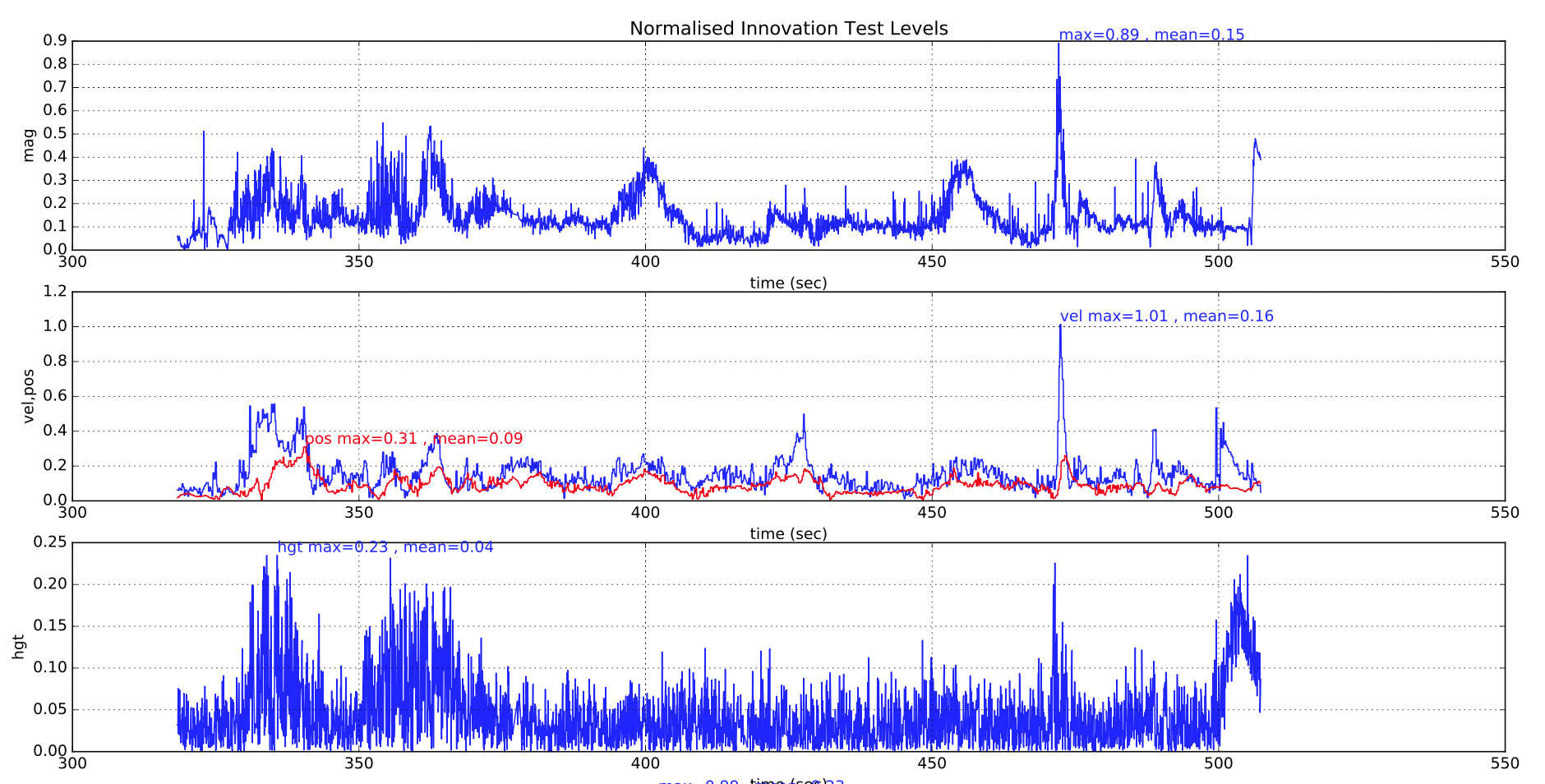
During normal operation, all the test ratios should remain below 0.5 with only occasional spikes above this as shown in the example below from a successful flight:
The following plot shows the EKF vibration metrics for a multirotor with good isolation. The landing shock and the increased vibration during takeoff and landing can be seen. Insufficient data has been gathered with these metrics to provide specific advice on maximum thresholds.
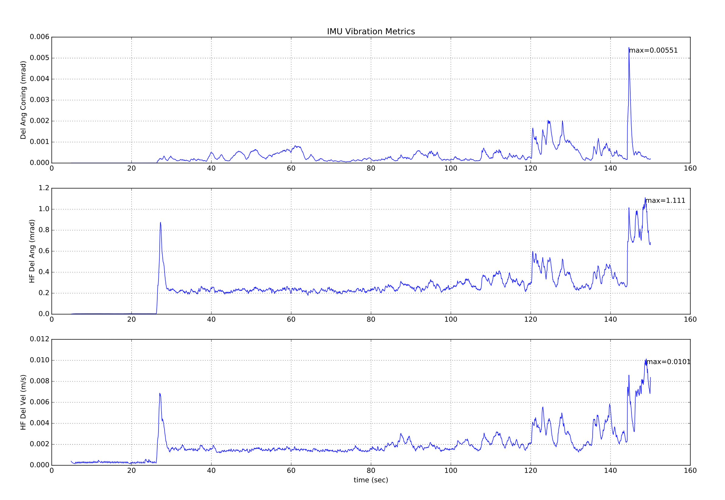
The above vibration metrics are of limited value as the presence of vibration at a frequency close to the IMU sampling frequency (1 kHz for most boards) will cause offsets to appear in the data that do not show up in the high frequency vibration metrics. The only way to detect aliasing errors is in their effect on inertial navigation accuracy and the rise in innovation levels.
In addition to generating large position and velocity test ratios of > 1.0, the different error mechanisms affect the other test ratios in different ways:
# 과도한 진동 여부 결정
High vibration levels normally affect vertical position and velocity innovations as well as the horizontal components. Magnetometer test levels are only affected to a small extent.
(insert example plots showing bad vibration here)
# 과도한 자이로 바이어스 결정
Large gyro bias offsets are normally characterised by a change in the value of delta angle bias greater than 5E-4 during flight (equivalent to ~3 deg/sec) and can also cause a large increase in the magnetometer test ratio if the yaw axis is affected. Height is normally unaffected other than extreme cases. Switch on bias value of up to 5 deg/sec can be tolerated provided the filter is given time settle before flying. Pre-flight checks performed by the commander should prevent arming if the position is diverging.
(insert example plots showing bad gyro bias here)
# 낮은 요 정확도 결정
Bad yaw alignment causes a velocity test ratio that increases rapidly when the vehicle starts moving due inconsistency in the direction of velocity calculated by the inertial nav and the GPS measurement. Magnetometer innovations are slightly affected. Height is normally unaffected.
(insert example plots showing bad yaw alignment here)
# 낮은 GPS 정확도 결정
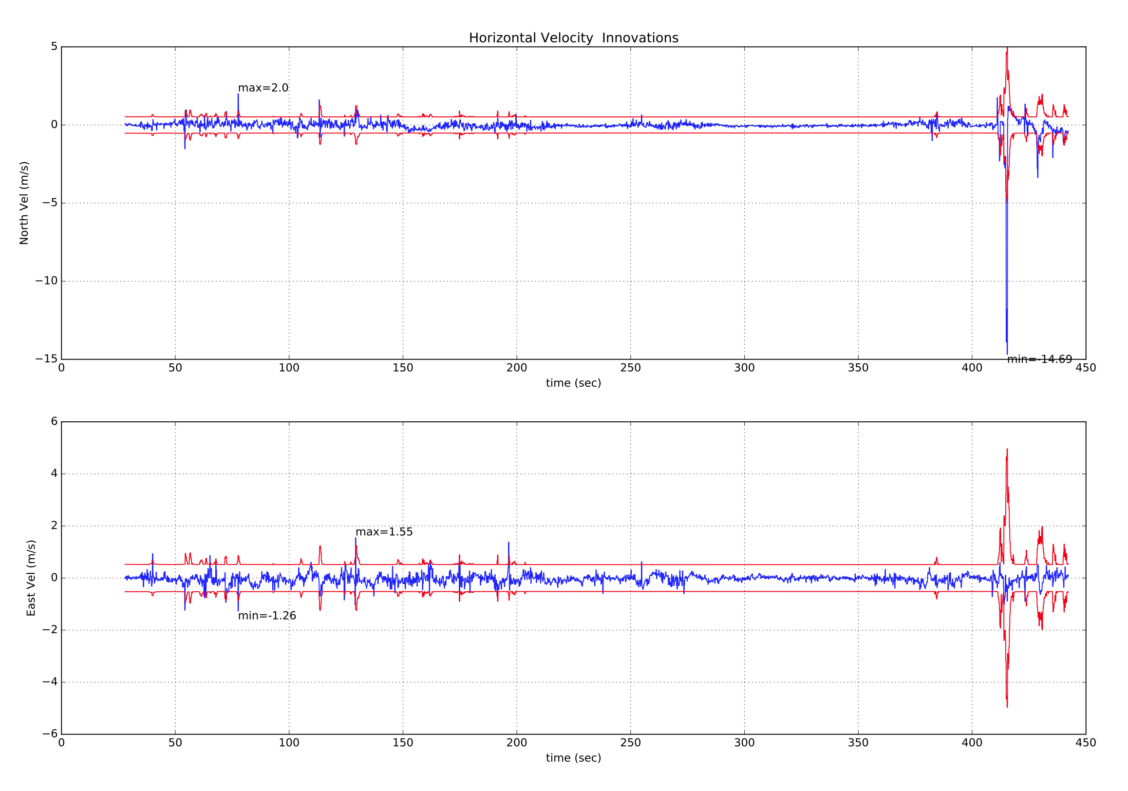
Poor GPS accuracy is normally accompanied by a rise in the reported velocity error of the receiver in conjunction with a rise in innovations. Transient errors due to multipath, obscuration and interference are more common causes. Here is an example of a temporary loss of GPS accuracy where the multi-rotor started drifting away from its loiter location and had to be corrected using the sticks. The rise in estimator_status (opens new window).vel_test_ratio to greater than 1 indicates the GPs velocity was inconsistent with other measurements and has been rejected.
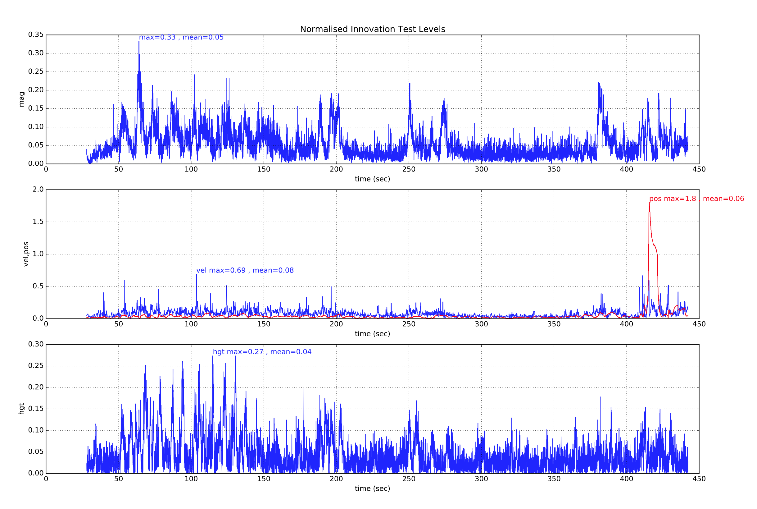
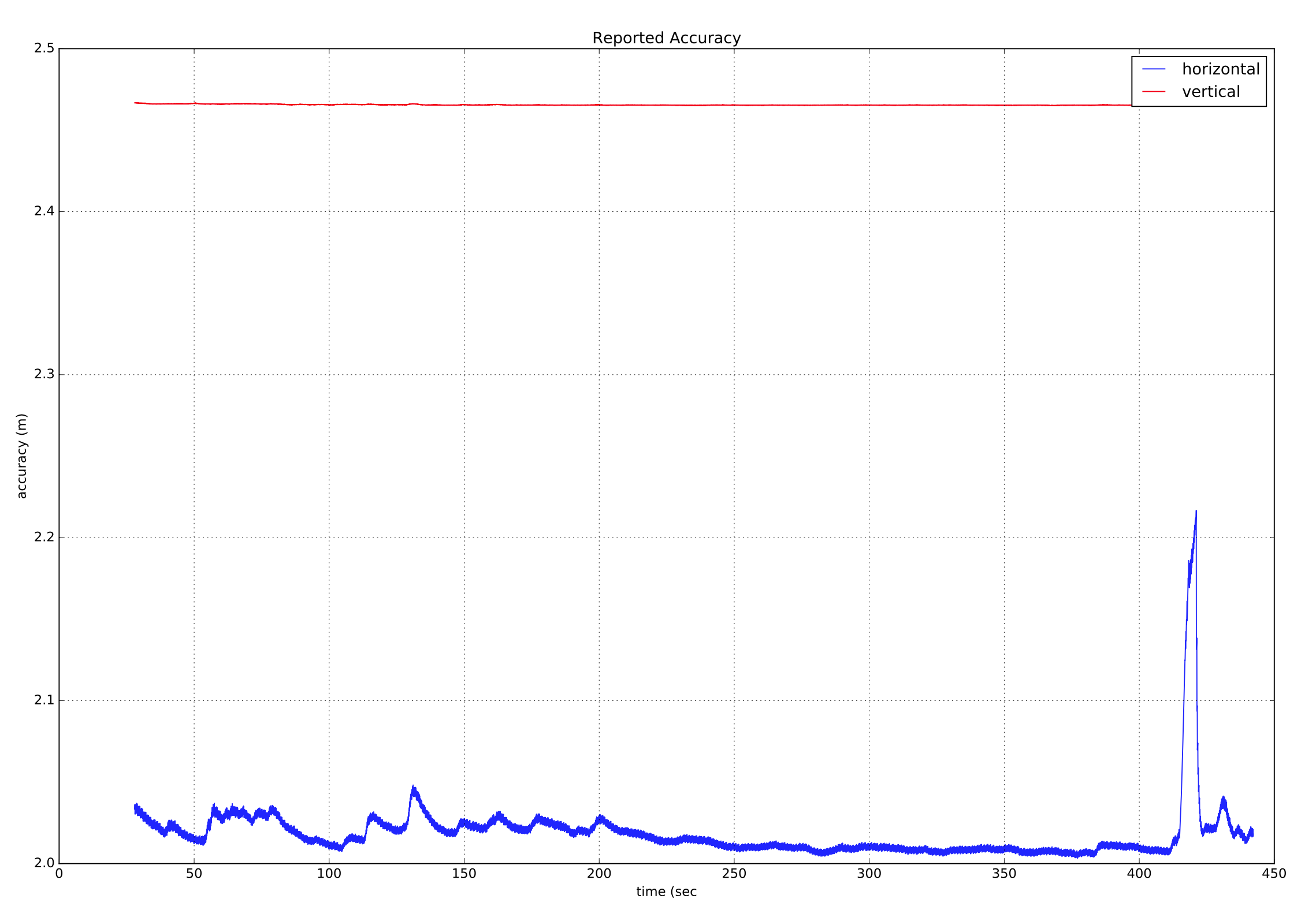
This is accompanied with rise in the GPS receivers reported velocity accuracy which indicates that it was likely a GPS error.
If we also look at the GPS horizontal velocity innovations and innovation variances, we can see the large spike in North velocity innovation that accompanies this GPS 'glitch' event.
# GPS 데이터 손실 결정
Loss of GPS data will be shown by the velocity and position innovation test ratios 'flat-lining'. If this occurs, check the other GPS status data in vehicle_gps_position for further information.
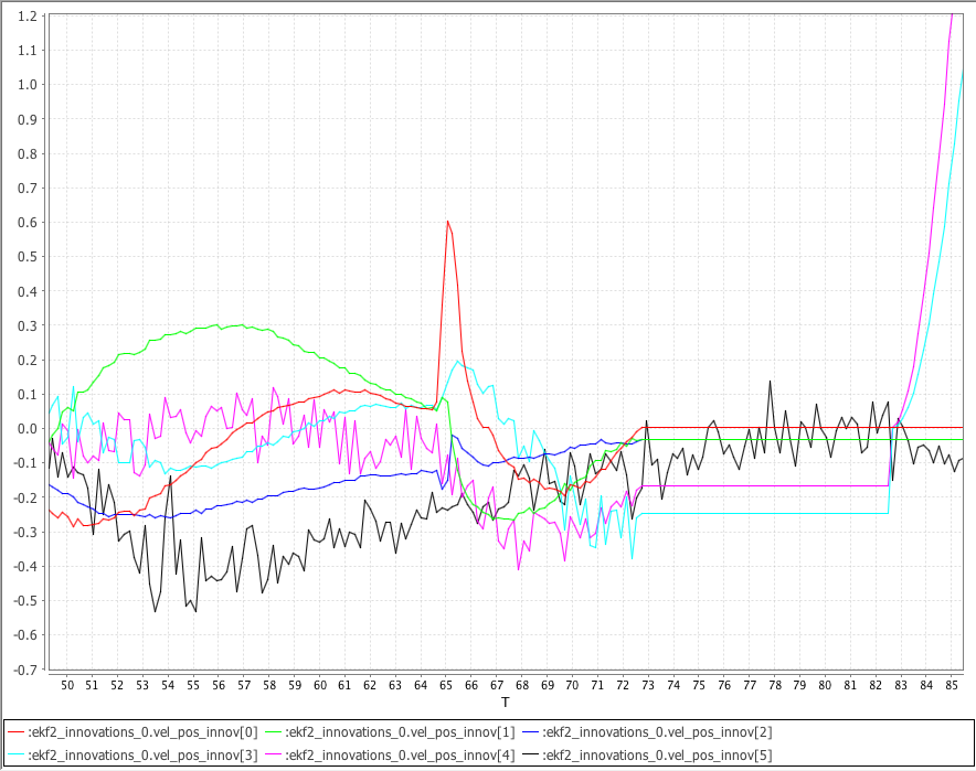
The following plot shows the NED GPS velocity innovations ekf2_innovations_0.vel_pos_innov[0 ... 2], the GPS NE position innovations ekf2_innovations_0.vel_pos_innov[3 ... 4] and the Baro vertical position innovation ekf2_innovations_0.vel_pos_innov[5] generated from a simulated VTOL flight using SITL Gazebo.
The simulated GPS was made to lose lock at 73 seconds. Note the NED velocity innovations and NE position innovations 'flat-line' after GPS is lost. Note that after 10 seconds without GPS data, the EKF reverts back to a static position mode using the last known position and the NE position innovations start to change again.
# 기압계 지면 효과 보상
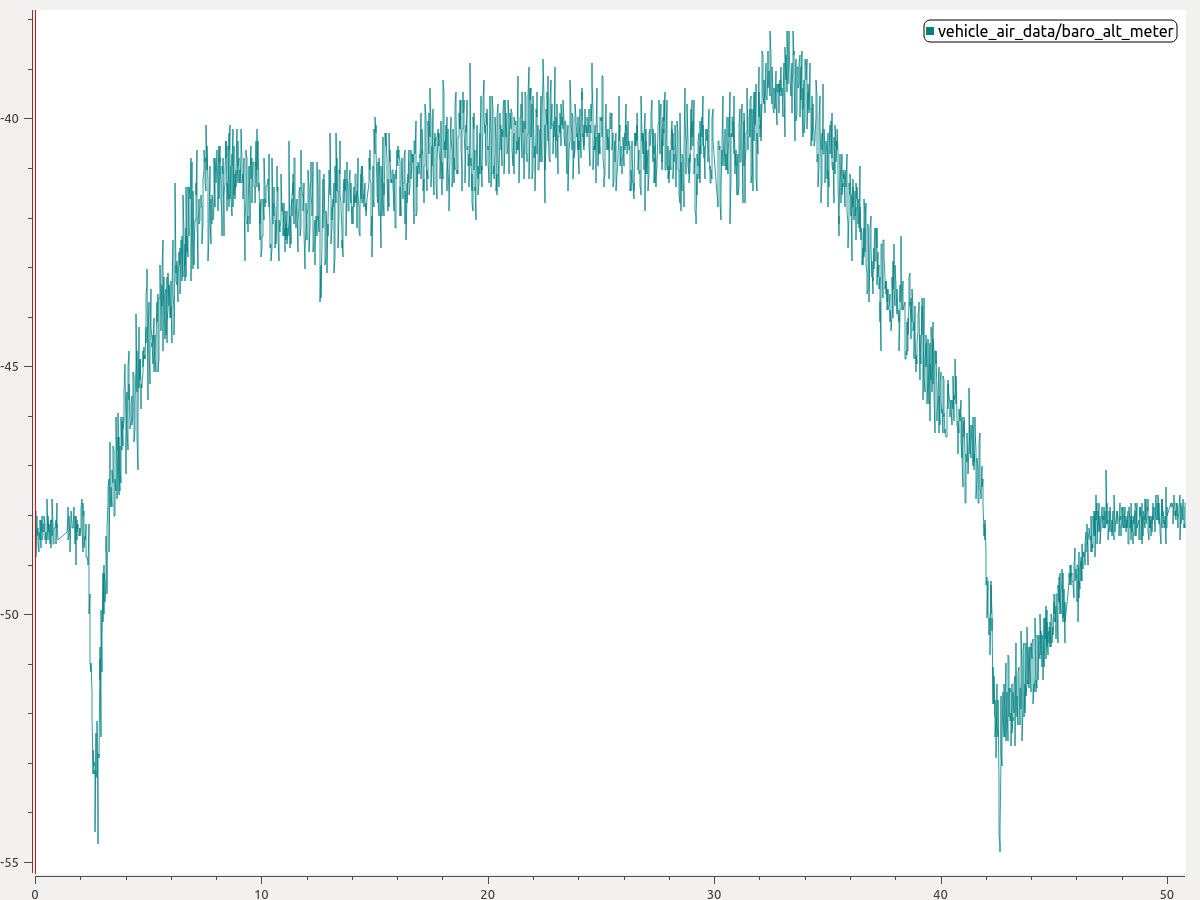
If the vehicle has the tendency during landing to climb back into the air when close to the ground, the most likely cause is barometer ground effect.
This is caused when air pushed down by the propellers hits the ground and creates a high pressure zone below the drone. The result is a lower reading of pressure altitude, leading to an unwanted climb being commanded. The figure below shows a typical situation where the ground effect is present. Note how the barometer signal dips at the beginning and end of the flight.
You can enable ground effect compensation to fix this problem:
- 플롯에서 이륙 또는 착륙중 기압계 하락의 크기를 추정합니다. 위의 플롯에서 착륙중 약 6 미터의 기압계 딥을 읽을 수 있습니다.
- 그런 다음 EKF2_GND_EFF_DZ 매개변수를 해당 값으로 설정하고 10% 여백을 추가하십시오. 따라서, 이 경우 6.6 미터 값이 좋은 출발점이 됩니다.
If a terrain estimate is available (e.g. the vehicle is equipped with a range finder) then you can additionally specify EKF2_GND_MAX_HGT, the above ground-level altitude below which ground effect compensation should be activated. If no terrain estimate is available this parameter will have no effect and the system will use heuristics to determine if ground effect compensation should be activated.
# 추가 정보
- PX4 State Estimation Overview (opens new window), PX4 Developer Summit 2019, Dr. Paul Riseborough): Overview of the estimator, and major changes from 2018/19, and the expected improvements through 2019/20.