# Pixhawk 3 Pro
PX4 does not manufacture this (or any) autopilot. Contact the [manufacturer](https://store-drotek.com/) for hardware support or compliance issues.
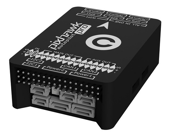
The Pixhawk® 3 Pro is based on the FMUv4 hardware design (Pixracer) with some upgrades and additional features. The board was designed by Drotek® (opens new window) and PX4.
注解
The main hardware documentation is here: https://drotek.gitbook.io/pixhawk-3-pro/hardware
提示
This autopilot is supported by the PX4 maintenance and test teams.
# 总览
- Microcontroller: STM32F469; Flash size is 2MiB, RAM size is 384KiB
- ICM-20608-G gyro / accelerometer
- MPU-9250 gyro / accelerometer / magnetometer
- LIS3MDL compass
- Sensors connected via two SPI buses (one high rate and one low-noise bus)
- Two I2C buses
- Two CAN buses
- Voltage / battery readings from two power modules
- FrSky® Inverter
- 8 Main + 6 AUX PWM outputs (Separate IO chip, PX4IO)
- microSD (logging)
- S.BUS / Spektrum / SUMD / PPM input
- JST GH user-friendly connectors: same connectors and pinouts as Pixracer
# Where to buy
From Drotek store (opens new window) (EU) :
From readymaderc (opens new window) (USA) :
# 编译固件
提示
Most users will not need to build this firmware! It is pre-built and automatically installed by QGroundControl when appropriate hardware is connected.
To build PX4 for this target:
make px4_fmu-v4pro_default
# Debug调试端口
The board has FMU and IO debug ports as shown below.
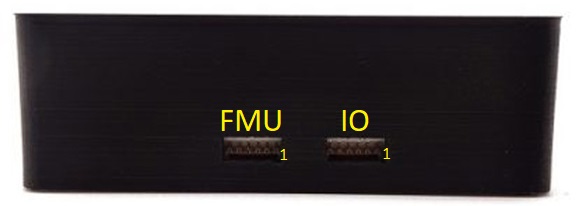
The pinouts and connector comply with the Pixhawk Standard Debug Port (opens new window) (JST SM06B connector).
| 针脚 | 信号 | 电压 |
|---|---|---|
| 2 | VCC TARGET SHIFT | +3.3V |
| 2 | UART7 Tx | +3.3V |
| 3 | UART7 Rx | +3.3V |
| 4(黑) | SWDIO | +3.3V |
| 6 | SWCLK | +3.3V |
| 6 | GND | GND |
For information about wiring and using this port see:
- PX4 System Console (Note, the FMU console maps to UART7).
- SWD (JTAG) Hardware Debugging Interface
# Serial Port Mapping
| UART | 设备 | Port |
|---|---|---|
| UART1 | /dev/ttyS0 | WiFi |
| USART2 | /dev/ttyS1 | TELEM1 (flow control) |
| USART3 | /dev/ttyS2 | TELEM2 (flow control) |
| UART4 | ||
| UART7 | CONSOLE | |
| UART8 | SERIAL4 |