# mRo Pixracer
PX4 does not manufacture this (or any) autopilot. Contact the [manufacturer](https://store.mrobotics.io/) for hardware support or compliance issues.
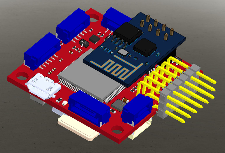
The Pixhawk® XRacer board family is optimized for small racing quads and planes. In contrast to Pixfalcon and Pixhawk it has in-built Wifi, new sensors, convenient full servo headers, CAN and supports 2M flash.

提示
This autopilot is supported by the PX4 maintenance and test teams.
# 主要特性
- Main System-on-Chip: STM32F427VIT6 rev.3 (opens new window)
- CPU: 180 MHz ARM Cortex® M4 with single-precision FPU
- RAM: 256 KB SRAM (L1)
- Standard FPV form factor: 36x36 mm with standard 30.5 mm hole pattern
- Invensense® ICM-20608 Accel / Gyro (4 KHz) / MPU9250 Accel / Gyro / Mag (4 KHz)
- HMC5983 magnetometer with temperature compensation
- Measurement Specialties MS5611 barometer
- JST GH connectors
- microSD (logging)
- Futaba S.BUS and S.BUS2 / Spektrum DSM2 and DSMX / Graupner SUMD / PPM input / Yuneec ST24
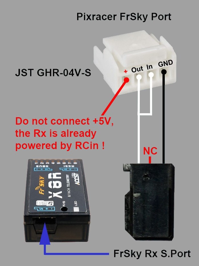
- FrSky® telemetry port
- OneShot PWM out (configurable)
- Optional: Safety switch and buzzer
# 在哪里买
Pixracer is available from the mRobotics.io (opens new window).
Accessories include:
- 数字空速传感器 (opens new window)
- HKPilot Transceiver Telemetry Radio Set V2 (915Mhz - US Telemetry) (opens new window)
- Hobbyking® OSD + EU Telemetry (433 MHz) (opens new window)
# Kit
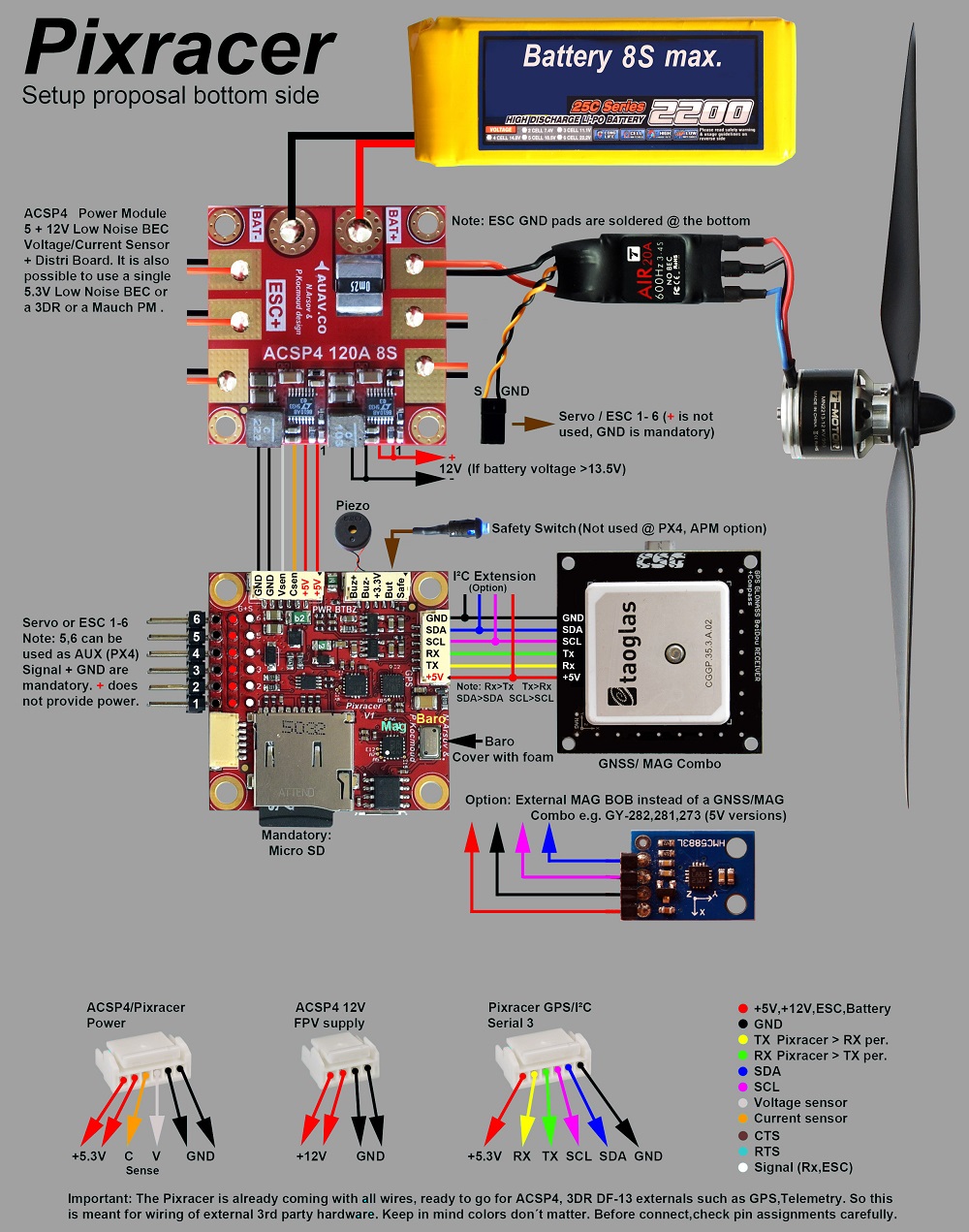
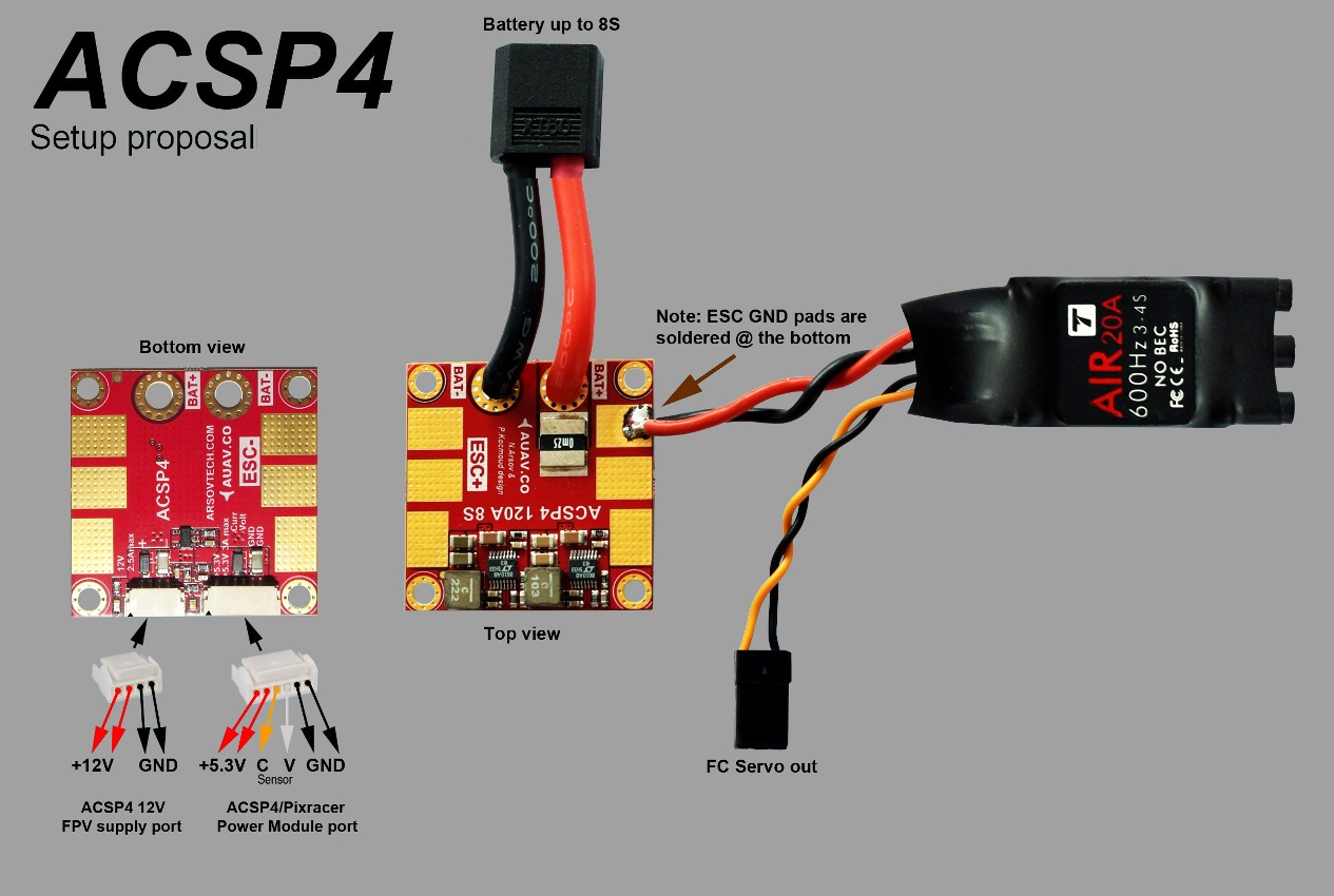
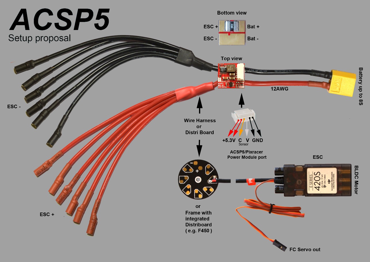
The Pixracer is designed to use a separate avionics power supply. This is necessary to avoid current surges from motors or ESCs to flow back to the flight controller and disturb its delicate sensors.
- Power module (with voltage and current sensing)
- I2C splitter (supporting AUAV, Hobbyking and 3DR® peripherals)
- Cable kit for all common peripherals
# Wifi (no USB required)
One of the main features of the board is its ability to use Wifi for flashing new firmware, system setup and in-flight telemetry. This frees it of the need of any desktop system.
::note ToDo Setup and telemetry are already available, firmware upgrade is already supported by the default bootloader but not yet enabled :::
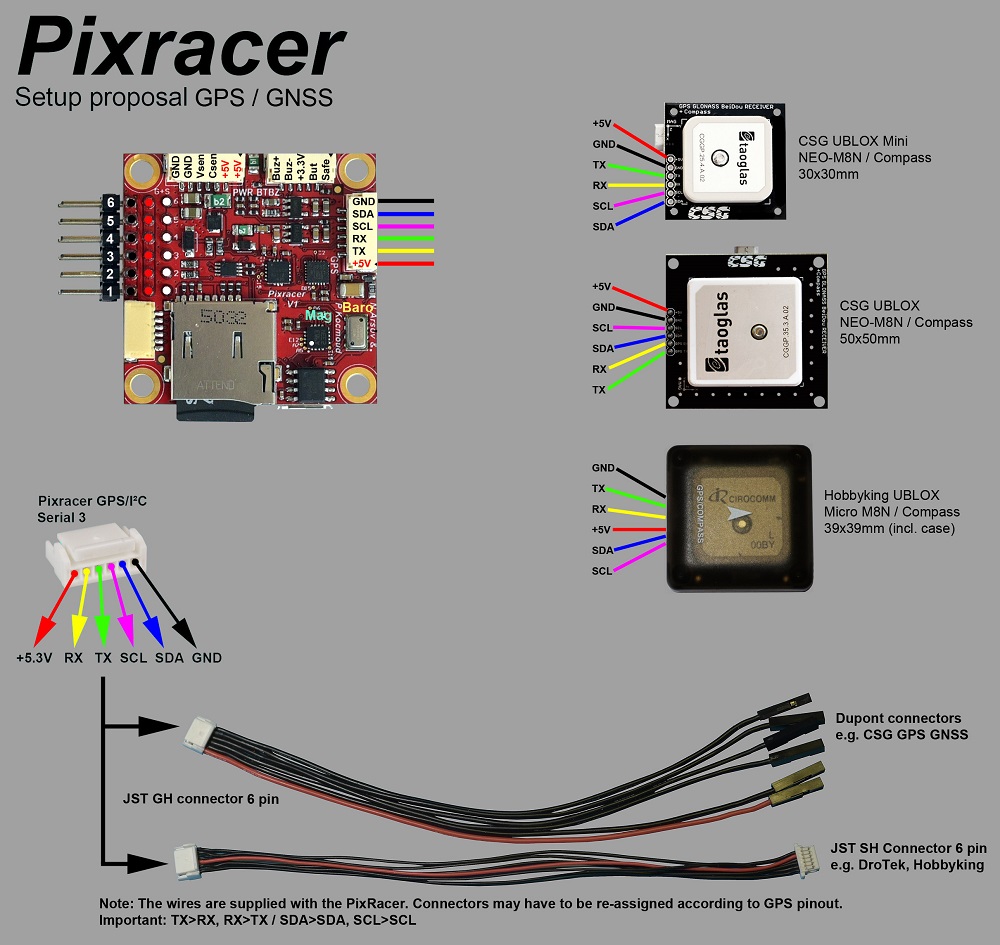
# Wiring Diagrams
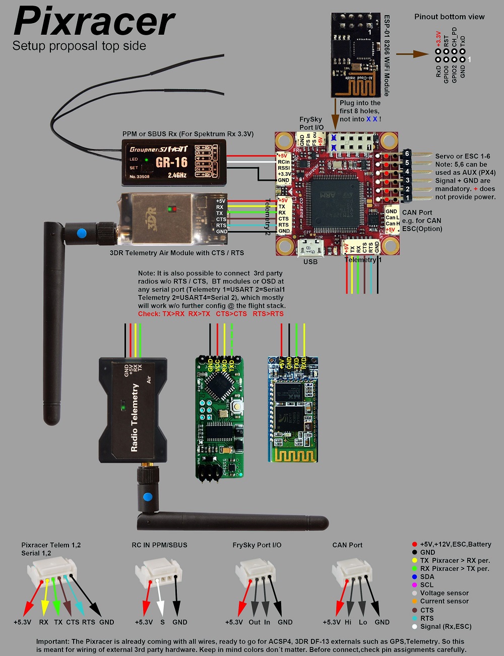
# 连接器
All connectors follow the Pixhawk connector standard (opens new window). Unless noted otherwise all connectors are JST GH.
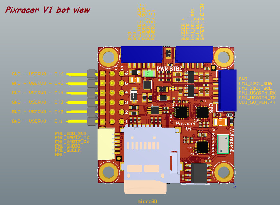
# 针脚定义
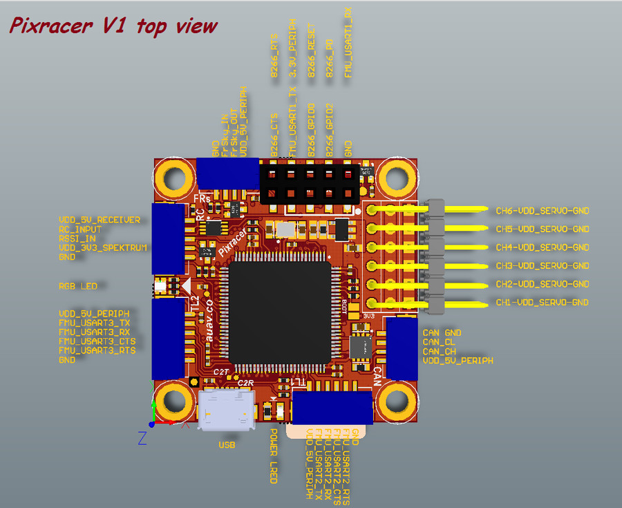
# TELEM1, TELEM2+OSD ports
| 针脚 | 信号 | 电压 |
|---|---|---|
| 2 | VCC | +5V |
| 2 | TX (OUT) | +3.3V |
| 3 | RX (IN) | +3.3V |
| 4(黑) | CTS (IN) | +3.3V |
| 6 | RTS (OUT) | +3.3V |
| 6 | GND | GND |
# GPS 接口
| 针脚 | 信号 | 电压 |
|---|---|---|
| 1(红) | VCC | +5V |
| 2(黑) | TX (OUT) | +3.3V |
| 3 | RX (IN) | +3.3V |
| 4(黑) | I2C1 SCL | +3.3V |
| 6 | I2C1 SDA | +3.3V |
| 6 | GND | GND |
# FrSky Telemetry / SERIAL4
| 针脚 | 信号 | 电压 |
|---|---|---|
| 2 | VCC | +5V |
| 2 | TX (OUT) | +3.3V |
| 3 | RX (IN) | +3.3V |
| 4(黑) | GND | GND |
# RC Input (accepts PPM / S.BUS / Spektrum / SUMD / ST24)
| 针脚 | 信号 | 电压 |
|---|---|---|
| 2 | VCC | +5V |
| 2 | RC IN | +3.3V |
| 3 | RSSI IN | +3.3V |
| 4(黑) | VDD 3V3 | +3.3V |
| 6 | GND | GND |
# CAN
| 针脚 | 信号 | 电压 |
|---|---|---|
| 2 | VCC | +5V |
| 2 | CAN_H | +12V |
| 3 | CAN_L | +12V |
| 4(黑) | GND | GND |
# POWER
| 针脚 | 信号 | 电压 |
|---|---|---|
| 2 | VCC | +5V |
| 2 | VCC | +5V |
| 3 | 电流 | +3.3V |
| 4(黑) | 电压 | +3.3V |
| 6 | GND | GND |
| 6 | GND | GND |
# SWITCH
| 针脚 | 信号 | 电压 |
|---|---|---|
| 2 | SAFETY | GND |
| 2 | !IO_LED_SAFETY | GND |
| 3 | VCC | +3.3V |
| 4(黑) | BUZZER- | - |
| 6 | BUZZER+ | - |
# Debug调试端口
This is a Pixhawk Debug Port (opens new window) (JST SM06B connector).
| 针脚 | 信号 | 电压 |
|---|---|---|
| 2 | VCC TARGET SHIFT | +3.3V |
| 2 | UART7 Tx | +3.3V |
| 3 | UART7 Rx | +3.3V |
| 4(黑) | SWDIO | +3.3V |
| 6 | SWCLK | +3.3V |
| 6 | GND | GND |
For information about wiring and using this port see:
- PX4 System Console (Note, the FMU console maps to UART7).
- SWD (JTAG) Hardware Debugging Interface
# Serial Port Mapping
| UART | 设备 | Port |
|---|---|---|
| UART1 | /dev/ttyS0 | WiFi (ESP8266) |
| USART2 | /dev/ttyS1 | TELEM1 (flow control) |
| USART3 | /dev/ttyS2 | TELEM2 (flow control) |
| UART4 | ||
| UART7 | CONSOLE | |
| UART8 | SERIAL4 |
# 原理图
The reference is provided as: Altium Design Files (opens new window)
The following PDF files are provided for convenience only:
- pixracer-rc12-12-06-2015-1330.pdf (opens new window)
- pixracer-r14.pdf (opens new window) - R14 or RC14 is printed next to the SDCard socket
# 编译固件
提示
Most users will not need to build this firmware! It is pre-built and automatically installed by QGroundControl when appropriate hardware is connected.
To build PX4 for this target:
make px4_fmu-v4_default
# 鸣谢
This design was created by Nick Arsov and Phillip Kocmoud and architected by Lorenz Meier, David Sidrane and Leonard Hall.