# PX4 참조 비행 콘트롤러 디자인
PX4 참조 디자인은 비행 콘트롤러의 Pixhawk 시리즈입니다. 2011년에 처음 출시된 이 디자인은 현재 5세대 세대입니다(6세대 보드 디자인 진행 중).
# 바이너리 호환성
특정 디자인으로 제조된 모든 보드는 바이너리 호환이 되어야 합니다(즉, 동일한 펌웨어를 실행하여야 함). 2018년부터 우리는 이 호환성을 확인하고 인증할 수 있는 바이너리 호환성 테스트 제품군을 제공할 것입니다.
FMU 1~3세대는 개방형 하드웨어로 설계되었으나, FMU 4세대와 5세대는 핀아웃 및 전원 공급 사양만 제공했습니다(개략도는 개별 제조업체에서 작성하였습니다). 우수한 호환성을 위하여 FMUv6 이상은 완전한 참조 디자인 모델링합니다.
# 레퍼런스 디자인 세대
- FMUv1: 개발 보드 (STM32F407, 128KB RAM, 1MB 플래시, 설계도 (opens new window))(PX4에서 더 이상 지원하지 않음)
- FMUv2: 픽스호크 (STM32F427, 168 MHz, 192 KB RAM, 1MB flash, 설계도 (opens new window))
- FMUv3: 2MB 플래시를 장착한 픽스호크 변형 버전 (3DR 픽스호크 2 (Solo), Hex 픽스호크 2.1, Holybro Pixfalcon, 3DR Pixhawk Mini, STM32F427, 168 MHz, 256 KB RAM, 2 MB flash, 설계도 (opens new window))
- FMUv4: 픽스레이서 (STM32F427, 168 MHz, 256 KB RAM, 2 MB flash, 핀 출력도 (opens new window))
- FMUv4 PRO: 드로텍 픽스호크 3 PRO (STM32F469, 180 MHz, 384 KB RAM, 2 MB flash, 핀 출력 (opens new window))
- FMUv5: 홀리브로 픽스호크 4 (STM32F765, 216 MHz, 512 KB RAM, 2 MB flash, 핀 아웃 (opens new window))
- FMUv6: 개발 중, 최종 명칭 미정, 6s 변형 (STM32H7, 400 MHz, 2 MB RAM, 2 MB flash)과 6i 변형 (i.MX RT1050, 600 MHz, 512 KB RAM, 외장 플래시)
# 메인 IO 기능 분석
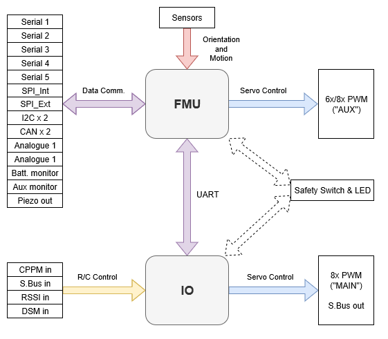
아래 다이어그램은 Pixhawk 시리즈 비행 콘트롤러의 FMU와 I/O 보드간 기능과 버스 분할을 나타냅니다(보드는 단일 물리적 모듈에 통합됨).

일부 Pixhawk 시리즈 컨트롤러는 공간이나 복잡성을 줄이기 위하여 특정 보드 의 기능 향상을 위하여 I/O 보드 없이 제작됩니다. In this case SYS_USE_IO is set to 0 so that the I/O driver is not started. You can also set SYS_USE_IO to 0 to disable the I/O on a flight controller where it is present but not needed (in order to slightly reduce the CPU load).
Note
I/O 보드가 없는 제조업체 비행 콘트롤러 변형은 종종 I/O 보드를 포함하는 버전의 "소형"으로 명명됩니다. 예 : Pixhawk 4 미니_, CUAV v5나노.
Build targets that must run on flight controllers with an I/O board map the FMU outputs to AUX and the I/0 outputs to MAIN (see diagram above). If the target is run on hardware where I/O board is not present or has been disabled, the PWM MAIN outputs will not be present. You might see this, for example, by running px4_fmu-v5_default on Pixhawk 4 (with IO) and Pixhawk 4 Mini (without I/O).
WARNING
On Pixhawk 4 Mini this results in a mismatch between the MAIN label screenprinted on the flight controller and the AUX bus shown during Actuator Configuration.
Note that if a build target is only ever intended to run on a flight controller that does not have an I/0 board, then the FMU outputs are mapped to MAIN (for example, the px4_fmu-v4_default target for Pixracer).
PX4 PWM outputs are mapped to either MAIN or AUX ports in Actuator Configuration.