CUAV V5+ Wiring Quick Start
This quick start guide shows how to power the CUAV V5+ flight controller and connect its most important peripherals.

Wiring Chart Overview
The image below shows how to connect the most important sensors and peripherals (except the motor and servo outputs). We'll go through each of these in detail in the following sections.

| Main interface | Function |
|---|---|
| Power1 | Connect power module. Power input with *ANALOG voltage and current detection. Do not use a Digital PM on this connector! |
| Power2 | Connect i2c smart battery. |
| TF CARD | SD card for log storage (card pre-inserted in factory). |
| M1~M8 | PWM outputs. Can be used to control motors or servos. |
| A1~A8 | PWM outputs .Can be used to control motors or servos. |
| DSU7 | Used for FMU debug, reading debug information. |
| I2C1/I2C2 | Connect an I2C device such as an external compass. |
| CAN1/CAN2 | Connect UAVCAN devices such as CAN GPS. |
| TYPE-C(USB) | Connect to a computer for communication between the flight controller and the computer, such as loading firmware. |
| SBUS OUT | Connect SBUS camera Gimbals |
| GPS&SAFETY | Connect to Neo GPS, which includes GPS, safety switch, buzzer interface. |
| TELEM1/TELEM2 | Connect to the Telemetry System. |
| DSM/SBUS/RSSI | Includes DSM, SBUS, RSSI signal input interface, DSM interface can be connected to DSM satellite receiver, SBUS interface to SBUS remote control receiver, RSSI for signal strength return module. |
For more interface information, please read V5+ Manual.

If the controller cannot be mounted in the recommended/default orientation (e.g. due to space constraints) you will need to configure the autopilot software with the orientation that you actually used: Flight Controller Orientation.
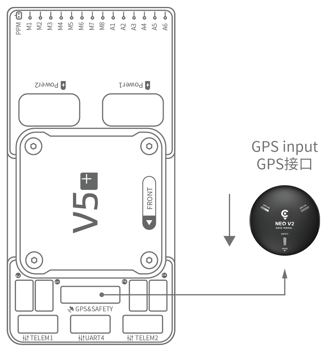
GPS + Compass + Safety Switch + LED
The recommended GPS module is the Neo v2 GPS, which contains GPS, compass, safety switch, buzzer, LED status light.
Other GPS modules may not work (see this issue).
The GPS/Compass module should be mounted on the frame as far away from other electronics as possible, with the direction marker towards the front of the vehicle (Neo v2 GPS arrow is in the same direction as the flight control arrow). Connect to the flight control GPS interface using a cable.
If you use CAN GPS, please use the cable to connect to the flight control CAN interface.
Safety Switch
The dedicated safety switch that comes with the V5+ is only required if you are not using the recommended Neo V2 GPS (which has an inbuilt safety switch).
If you are flying without the GPS you must attach the switch directly to the GPS1 port in order to be able to arm the vehicle and fly (if you use the old 6-pin GPS, please read the definition of the bottom interface to change the line).
Buzzer
If you do not use the recommended GPS, the buzzer may not work.
Radio Control
A remote control (RC) radio system is required if you want to manually control your vehicle (PX4 does not require a radio system for autonomous flight modes). You will need to select a compatible transmitter/receiver and then bind them so that they communicate (read the instructions that come with your specific transmitter/receiver).
The figure below shows how you can access your remote receiver (please find the SBUS cable in the kit).

Spektrum Satellite Receivers
The V5+ has a dedicated DSM cable. If using a Spektrum satellite receiver, this should be connected to the flight controller DSM/SBUS/RSSI interface.
Power
The V5+ kit includes the HV_PM module, which supports 2~10S LiPo batteries.
Connect the 6pin connector of the HW_PM module to the flight control Power1 interface.
The supplied power module is unfused (see this issue).
- Power must be turned off while connecting peripherals.
- Improper wiring can lead to personal harm or equipment damage!
The power module is not a power source for peripherals connected to the PWM outputs. If you're connecting servos/actuators you will need to separately power them using a BEC.
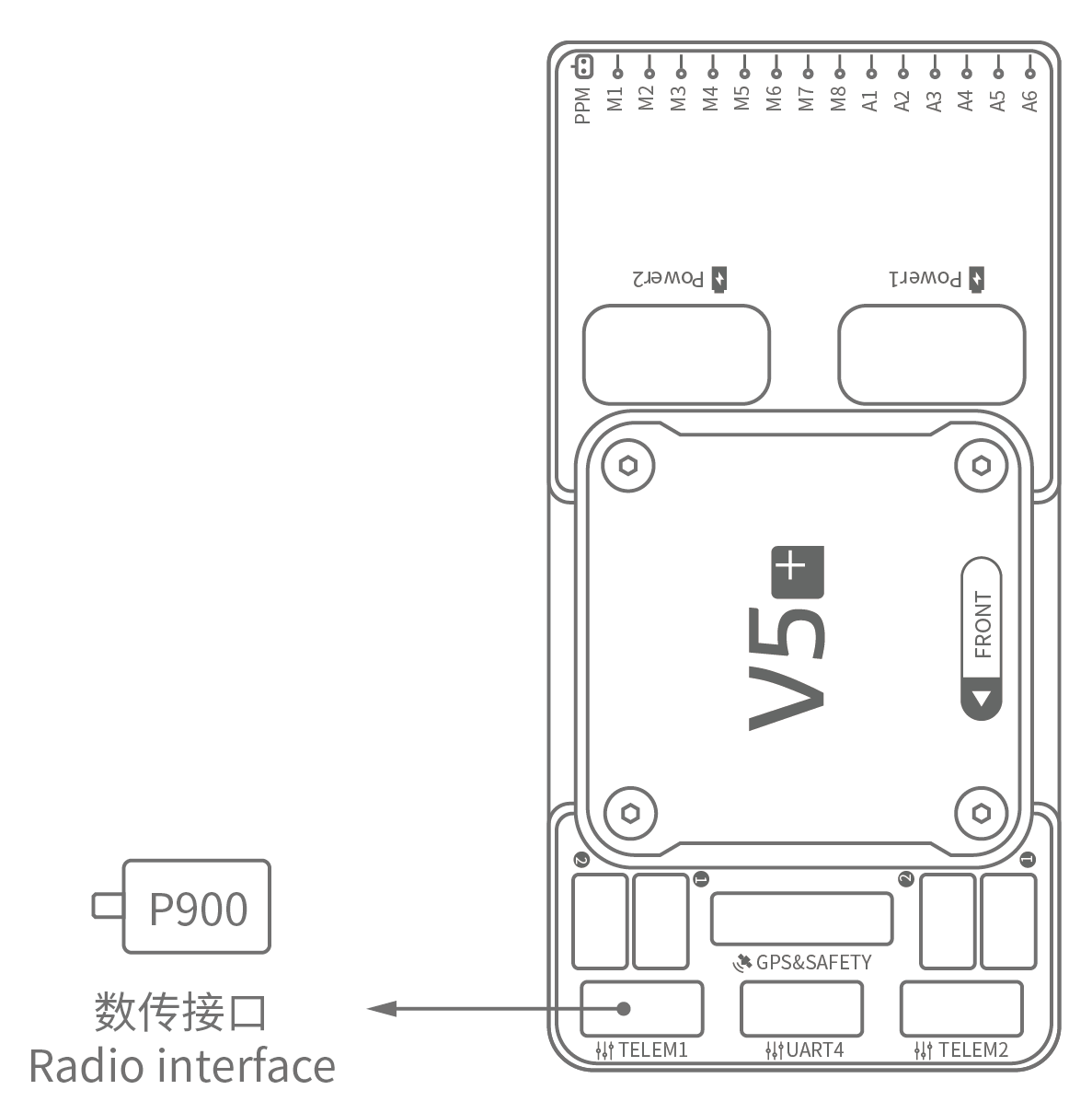
Telemetry System (Optional)
A telemetry system allows you to communicate with, monitor, and control a vehicle in flight from a ground station (for example, you can direct the UAV to a particular position, or upload a new mission).
The communication channel is via Telemetry Radios.
The vehicle-based radio should be connected to either the TELEM1 or TELEM2 port (if connected to these ports, no further configuration is required).
The other radio is connected to your ground station computer or mobile device (usually via USB).
SD Card (Optional)
An SD card is inserted in the factory (you do not need to do anything).
Motors
Motors/servos are connected to the MAIN and AUX ports in the order specified for your vehicle in the Airframes Reference.
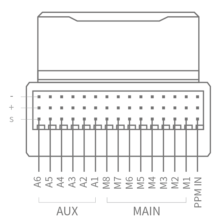
Pinouts
Download V5+ pinouts from here.
Further Information
- Airframe build-log using CUAV v5+ on a DJI FlameWheel450
- CUAV V5+ Manual (CUAV)
- CUAV V5+ docs (CUAV)
- FMUv5 reference design pinout (CUAV)
- CUAV Github (CUAV)
- Base board design reference (CUAV)