ESP8266 WiFi Module
The ESP8266 is a low-cost and readily available Wi-Fi module with full TCP/IP stack and microcontroller capability. It can be used with any Pixhawk series controller.
ESP8266 is the defacto default WiFi module for use with Pixracer (and is usually bundled with it).
Where to Buy
The module is readily available. A few vendors are listed below.
Module Setup
The ESP8266 firmware has these factory settings:
- SSID: PixRacer
- Password: pixracer
- WiFi Channel: 11
- UART speed 921600
Build From Sources
The firmware repository contains instructions and all the tools needed for building and flashing the firmware.
Pre Built Binaries
MavLink ESP8266 Firmware V 1.2.2
Updating the Firmware
If you have firmware 1.0.4 or greater installed, you can do the update using the ESP's Over The Air Update feature.
Just connect to its AP WiFi link and browse to: http://192.168.4.1/update.
You can then select the firmware file you downloaded above and upload it to the WiFi Module.
Flashing the ESP8266 Firmware
Before flashing, make sure you boot the ESP8266 in Flash Mode as described below. If you cloned the MavESP8266 repository, you can build and flash the firmware using the provided PlatformIO tools and environment. If you downloaded the pre-built firmware above, download the esptool utility and use the command line below:
esptool.py --baud 921600 --port /dev/your_serial_port write_flash 0x00000 firmware_xxxxx.bin
Where:
- firmware_xxxxx.bin is the firmware you downloaded above
- your_serial_port is the name of the serial port where the ESP8266 is connected to (
/dev/cu.usbmodemfor example)
Wiring for Flashing the Firmware
ESP8266 must be powered with 3.3 volts only.
There are various methods for setting the ESP8266 into Flash Mode but not all USB/UART adapters provide all the necessary pins for automatic mode switching. In order to boot the ESP8266 in Flash Mode, the GPIO-0 pin must be set low (GND) and the CH_PD pin must be set high (VCC). This is what my own setup looks like:

I built a cable where RX, TX, VCC, and GND are properly wired directly from the FTDI adapter to the ESP8266. From the ESP8266, I left two wires connected to GPIO-0 and CH_PD free so I can boot it either normally or in flash mode by connecting them to GND and VCC respectively.
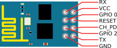
ESP8266 (ESP-01) Pinout
Flashing Diagram using an FTDI USB/UART Adapter

Pixhawk/PX4 Setup & Configuration
If using PX4 1.8.2 (and earlier) you should connect the ESP8266 to TELEM2 and configure the port by setting the parameter
SYS_COMPANIONto 1921600 (remember to reboot after setting the parameter). The following instructions assume you are using PX4 versions after 1.8.2
Connect your ESP8266 to your Pixhawk-series flight controller (e.g. Pixracer) on any free UART.
Connect the flight controller to your ground station via USB (as WiFi is not yet fully set up).
Using QGroundControl:
- Load recent PX4 firwmare
- Configure the serial port used to connect the ESP8266. Remember to set the baud rate to 921600 in order to match the value set for the ESP8266.
Once the firmware (port) is set up you can remove the physical USB connection between the ground station and the vehicle.
Connect via ESP8266 to QGC
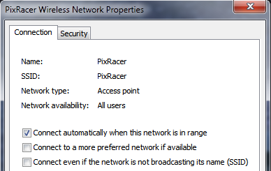
On your wifi-enabled QGroundControl ground station computer/tablet, find and connect to the open wireless network for your ESP8266.
- By default the ESP8266 network is named PixRacer and the default password is pixracer.
On Windows, the connection settings will look like this:

QGC automatically starts its UDP link on boot. Once your computer/tablet is connected to the PixRacer WiFi Access Point, it will automatically make the connection.
You should now see HUD movement on your QGC computer via wireless link and be able to view the summary panel for the ESP8266 WiFi Bridge (as shown below).

If you have any problem connecting, see QGC Installation/Configuration Problems.