Lumenier QAV250 Pixhawk Mini Build
The Lumenier QAV250 Mini FPV Quadcopter is a small but fully functional FPV multicopter frame. This topic provides full build and configuration instructions for using the frame with the Pixhawk Mini flight controller, including how to install and configure the PX4 autopilot using QGroundControl.
Key information
- Frame: Lumenier QAV250 CF
- Flight controller: Pixhawk Mini
- Assembly time (approx.): 3.5 hours (2 for frame, 1.5 autopilot setup)

Bill of materials
The components used in this build are listed below (along with links to where they can be purchased). In general we used hardware recommended by the manufacturers for the flight controller and frame.
- Flight controller: Pixhawk Mini (Discontinued)
- Power module: 3DR 10s Power Module (Discontinued)
- ESC: Lumenier f390 with Blheli (getfpv.com). These come with the motors.
- Motors: Lumenier RX2204 -14 2300KV (getfpv.com)
- Propellers: Lumenier 5x4.5 2 blade (getfpv.com)
- Frame: Lumenier QAV250 - CF (getfpv.com)
- Receiver: FR SKY D4R-II (getfpv.com)
- Battery: Lumenier 4S 1300 mAh (getfpv.com)
Notes:
- The 4S Power Module that comes with the Pixhawk Mini can be used for the battery size above (instead of the 10S Power Module). Assembly is the same with either power module.
- We also recommend these ESC: Lumenier 12 amp ESC w/ SimonK AutoShot (2-4s N-FET) (getfpv.com).
Hardware
This section lists all hardware for the frame and the autopilot installation.
Frame QAV250
| Description | Quantity |
|---|---|
| Unibody frame plate | 1 |
| Flight controller cover plate | 1 |
| PDB | 1 |
| Camera plate | 1 |
| 35mm standoffs | 6 |
| 25mm standoffs | 4 |
| 10mm standoffs | 4 |
| Vinyl caps | 4 |
| 20mm steel screws | 4 |
| 18mm steel screws | 10 |
| Velcro battery strap | 1 |
| Foam for battery | 1 |
| LEDs strip | 2 |

Electronics
| Description | Quantity |
|---|---|
| Motors lumenier Rx2204-14 2300KV | 4 |
| ESC lumenier 30A | 4 |
| 3DR power module 10S | 1 |
| Fr-sky D4R-II receiver | 1 |
| 3DR Pixhawk Mini autopilot | 1 |
| 3DR GPS Neo-M8N | 1 |
| 8 PWM servo output | 1 |
| External safety switch | 1 |
| Micro SD card | 1 |
| Battery Lumenier 1300 mAh 4S 14.8V | 1 |

Telemetry radio (optional)
A telemetry radio is an optional component that can be used to wirelessly connect a ground control station (GCS) computer with the autopilot. This allows you to view in-flight data, change missions on the fly, and tune in the vehicle during flight.
PX4/Pixhawk Mini support many different telemetry radios. The radio used in this build is the (highly recommended) 3DR Telemetry Radio (915MHz) (Discontinued).
Telemetry radios use different frequency bands in order to comply with local regulations. Select a version appropriate for your region: USA - 915 MHz, Europe/Australia - 433MHz
The telemetry kit includes:
- Two telemetry transceivers (for vehicle and GCS)
- Micro USB cable
- Android OTG adapter cable
- Double-sided tape

Assembly tools
The following tools are used in this assembly:
- 2.0mm Hex screwdriver
- 3mm Philips screwdriver
- Wire cutters
- Soldering iron and solder
- Precision tweezers

Off-frame assembly
This section shows how the electronics are wired (off frame) and how the frame is assembled without the electronics. This information can be used for reference if the on-the-frame screenshots are not sufficiently clear.
Electronics Wiring/Connections (off frame)
The image below shows the standard multicopter wiring for Pixhawk Mini. It uses the Quad Power Distribution Board to power the ESCs, Pixhawk and Pixhawk power rail (the board includes an integrated power module that supports batteries up to 4S).
For this QAV250 build we instead use the separate 10S Power module to power the ESCs and Pixhawk, and we don't use the optional external switch. The wiring is otherwise similar!

Frame-only assembly
This section shows how the frame is assembled without the complication of the electronics. It is references in the full assembly documentation below.
To assemble the frame:
Step 1: Use the 10mm standoffs and 20mm steels screws for PDB as shown in the picture.

Step 2: Place the frame on the standoffs.

Ensure that you have the frame-plate mounted the correct way. This cut indicated below shows the bottom of the frame.

Step 3: Put the 35mm standoffs on the screws (you will need 2.0mm Hex screwdriver).

Step 4: Attach the camera plate and add remaining standoffs.
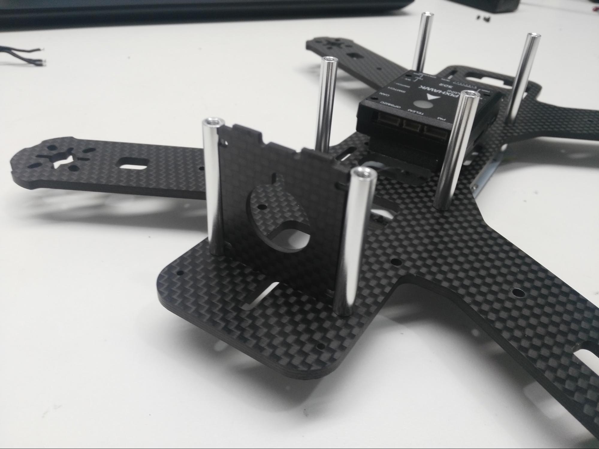
Step 5: Place the flight controller cover plate on the standoffs and screw into place.

Additional/manufacturer assembly can be found here: Lumenier QAV250 Carbon Fiber Build Manual.
FULL Assembly with electronics
This section describes the full assembly of the QAV250 along with the Pixhawk Mini, motors and other electronics.
Step 1: Install motors
The red mark indicates the front of the frame. Make sure you place the motors in the correct order on the frame and pass the cables through the bottom of the frame.

Step 2: Solder the 4 ESCs to the PDB
The red cables must be soldered to the positive pad and the black cables to the negative pad (as shown for a single ESC below).

Step 3: Solder the power module to the PDB
The red cable should be soldered to the positive pad and the black cable to the negative pad. Solder in a way that fits your build.

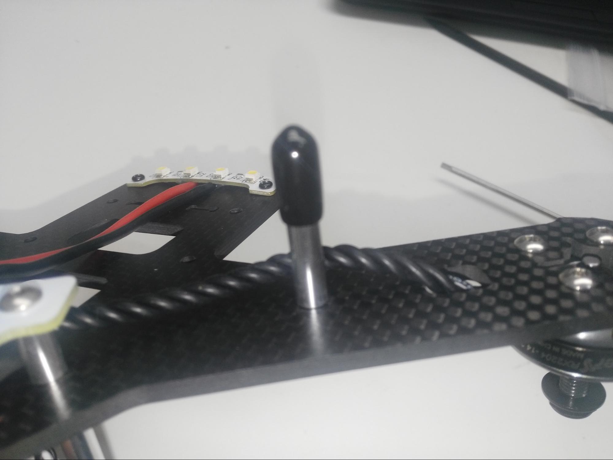
Step 4: Solder LEDs to the PDB
Red cables should connect to the positive pad and black cables with negative pads. The white LEDs are for the front and the red LEDs are for back.

Step 5: Solder the motors with the ESC
Solder the motor cables to the ESC pads as shown below. Make sure the motors turns in the correct direction. If not, swap the positions of cables A and C on the ESC.
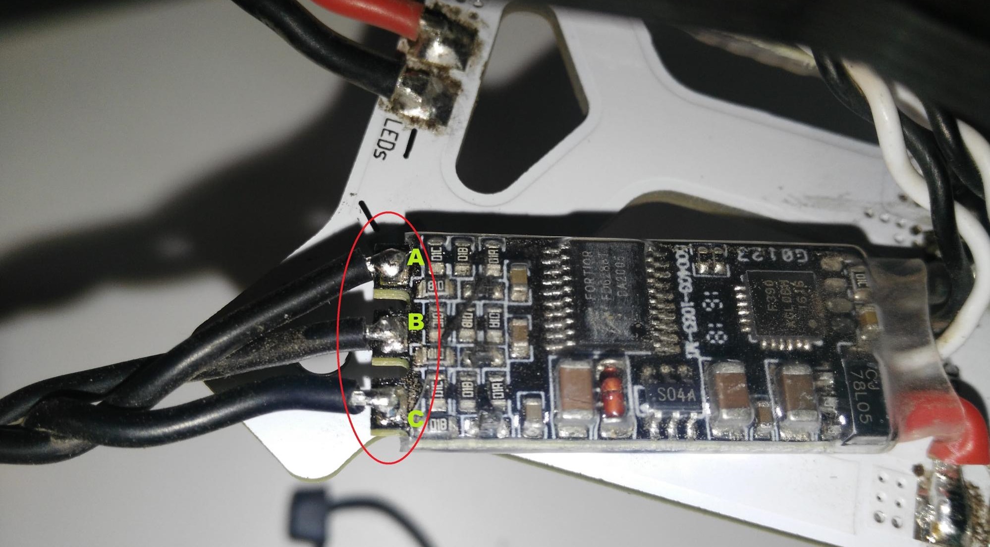
Once the cables are soldered in the correct order, cover the pads with electrical tape or tubing.

Step 6: Attach the PDB to the frame
Follow the steps described in the Frame assembly section.

Step 7: Attach the LEDs to the frame using the Phillips screws provided.

The carbon fiber is conductive use silicon to avoid the contact with the weld in the frame.

Step 8: Attach vibration damping foam to the frame as shown (the foam is included in the Pixhawk Mini kit).
The foam reduces vibrations that may otherwise affect Pixhawk performance. The foam is sticky on both sides.

Step 9: Attach the Pixhawk Mini to the frame using the damping foam.
The Pixhawk should be oriented so that the arrow faces the front of the frame.

Step 10: Connect the power module.
Connect the Power Module and Pixhawk Mini using the supplied 6pin cable (as shown). If you're using the Power Module from the Pixhawk Mini kit it is connected in the same way.

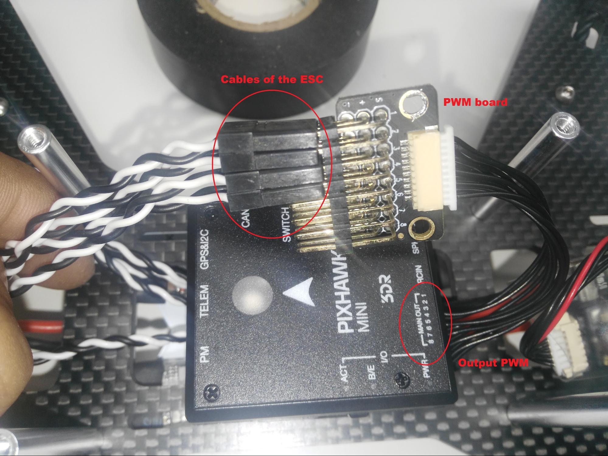
Step 11: Connect ESC to the PWM output
Attach the ESCs to the Pixhawk Mini in the correct order, using either a PWM output cable or a PWM board as shown below (both are supplied in the Pixhawk Mini kit ).

Step 12: Connect the receiver
Connect the FRSky D4-R receiver channel 1 to the RCIN port on the Pixhawk Mini (as shown).

Notes on receivers:
- The Pixhawk Mini RCIN port accepts PPM input (i.e. multiplexed channels). You can use a PWM receiver (with individual cables for each channel) but you will have to connect via PPM encoder like this one.
- You can also use a Spektrum receiver. These are connected to the SPKT/DSM input next to RCIN on the Pixhawk Mini.
- For more information see: Pixhawk Mini Receiver Compatibility
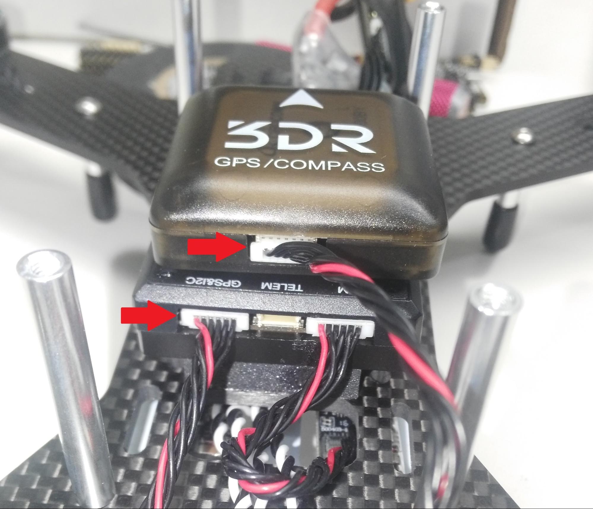
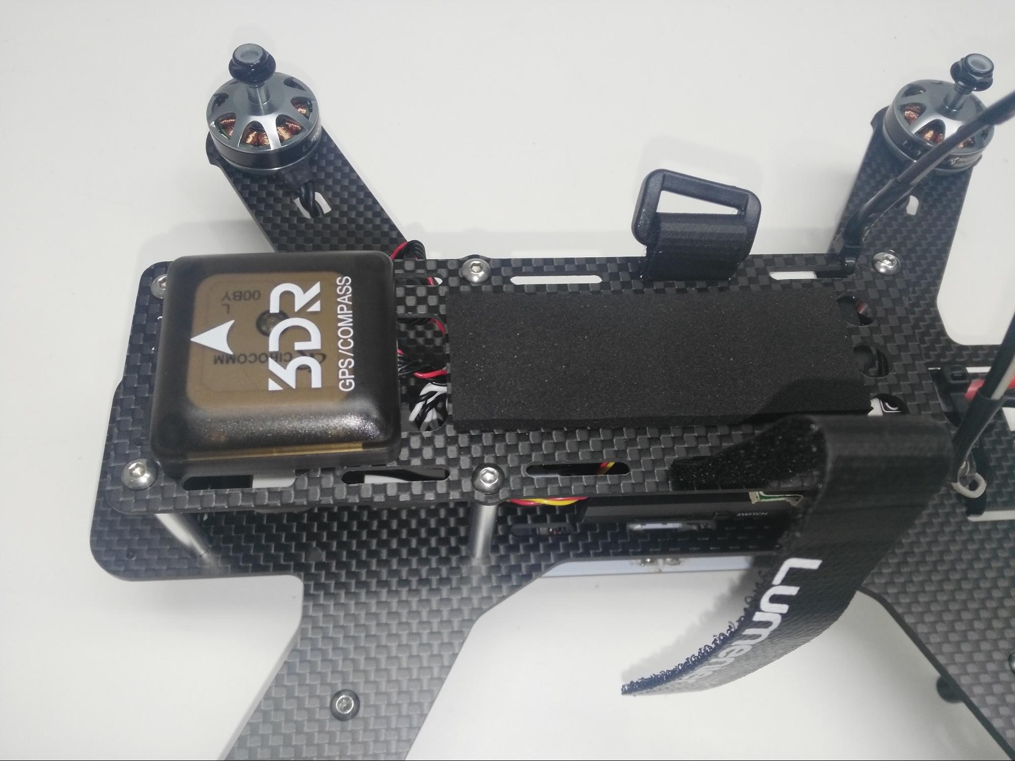
Step 13: Connect the GPS/COMPASS module
Connect the GPS/COMPASS module to the Pixhawk Mini's GPS&I2C port as shown below.
Step 14: Mount the GPS/COMPASS module
Attach flight controller cover plate (see frame assembly instructions) and then paste the GPS module onto the cover plate with the arrow to the front (paste included in kit).

Step 15: Connect and mount the telemetry radio (Optional)
Connect the telemetry radio to the Pixhawk Mini TELEM port as shown.

Then mount the radio using the double-sided tape included in the telemetry radio kit (for this build we mounted the radio below the PDB, as shown below).

Step 16: Attach landing standoffs to the arms
Step 17: Attach the battery foam and velcro battery strap to the cover plate (the battery strap and foam come with the frame kit)
The frame build is now complete! In the next step we can install and configure the PX4 autopilot.
PX4 installation and configuration
This section explains how you can use QGroundControl to install the PX4 autopilot and configure/tune it for the QAV250 frame.
QGroundControl can be used to install and configure your autopilot, and also to plan missions and control your vehicle remotely.
Download and install QGroundControl for your platform.
Firmware update
Update the Pixhawk Mini with the PX4 firmware, configured for the Lumenier QAV250.
Step 1: Start QGroundControl and select Firmware from the sidebar. Connect your vehicle to the USB port

Step 2: Select the airframe (Quadrotor x > Lumenier QAV250).
Then click Apply and Restart.

For additional information see:
- Autopilot Configuration
- Firmware setup (QGroundControl)
Vehicle calibration/setup
Vehicle calibration/setup is typically similar for all vehicles. You can follow the instructions below, or see Autopilot Configuration.
Step 3: Radio calibration
- Turn on the remote control.
- Select Radio in the left-sidebar.
- Select the "mode" of your remote control (top right).
- Click the Calibrate button and follow the on-screen instructions.

Step 4: Calibrate sensors
- Select Sensors in the left-sidebar.
- Select the Compass button and then follow the on-screen instructions.
- Select the Gyroscope button and then follow the on-screen instructions.
- Select the Accelerometer button and then follow the on-screen instructions.

Step 5: Select flight modes.
Flight Modes provide autopilot assisted or fully controlled flight. New users should configure their receiver to support the following three modes (these make the vehicle much easier to fly):
- Stabilized - Vehicle hard to flip, and will level-out if the sticks are released (but not hold position)
- Altitude - Climb and drop are controlled to have a maximum rate.
- Position - When sticks are released the vehicle will stop (and hold position against wind drift)
There are a number of ways to configure flight modes. In this case we have a three-way switch on the receiver that we map to a single channel (5).

For more information see:
- Flight Mode Configuration
- Flight Modes
- Flight Modes (QGroundControl)
Step 6: Calibrate ESC
Remove propellers.
Propellers must be removed from vehicle prior to performing ESC calibration!
- Select Power in the left-sidebar.
Select the Calibrate button and then follow the on-screen instructions (Connect your battery. When the tones stop, press OK and unplug battery).


Tuning
Firmware installation sets default autopilot parameters that have been configured for the selected frame (in this case for the Lumenier QAV250). As builds may use different components and place them differently, it is a good idea to tune the parameters for a specific frame build.
The parameters below are recommended for this build (the yellow parameters are the ones that have changed). These were generated by flight testing.

For general information on tuning see: Multicopter PID Tuning Guide.
Video
The video below shows this QAV250 on a test flight.
Acknowledgements
This build log was provided by: Abimael Suarez, 3DRobotics. Video was provided by Santiago Escala, 3DRobotics.