# Holybro X500 V2 (Pixhawk 5X Build)
This topic provides full instructions for building the Holybro X500 V2 ARF Kit (opens new window) and configuring PX4 using QGroundControl.
The ARF ("Almost Ready to Fly") kit provides the shortest and straightforward assembly experience for those who want to jump into drone development and not spend that much time on setting up the hardware. It includes the frame, motors, ESCs, propellers and power distribution board.
In addition to the kit you will need to have the flight controller, radio transmitters, GPS and RC controller. The ARF kit can be used with most flight controllers supported by PX4.
# Key information
- Kit: Holybro X500 V2 ARF Kit (opens new window)
- Flight controller: Pixhawk 5X
- Assembly time (approx.): 55 min (25 minutes for frame, 30 minutes for autopilot installation/configuration)
# Bill of materials
The Holybro X500 V2 Kit (opens new window) includes almost all the required components:
- X500V2 Frame Kit
- Body - Full Carbon Fiber Top & Bottom plate (144 x 144mm, 2mm thick)
- Arm - High strength & ultra-lightweight 16mm carbon fiber tubes
- Landing gear - 16mm & 10mm diameter carbon fiber tubes
- Platform board - With mounting holes for GPS & popular companion computer
- Dual 10mm Ø rod x 250 mm long rail mounting system
- Battery mount with two Battery Straps
- Hand tools for installation
- Holybro Motors - 2216 KV880 x6 (opens new window)
- Holybro BLHeli S ESC 20A x4 (opens new window)
- Propellers - 1045 x4 (opens new window)
- Power Distribution Board – XT60 plug for battery & XT30 plug for ESCs & peripherals
- Camera mount (optional and the 3D file can be downloaded from here (opens new window))
Other parts in this build(Not included in the ARF kit):
- Pixhawk 5X autopilot
- M8N GPS (opens new window)
- Power Module - PM02D (opens new window)
- 433/915 MHz Telemetry Radio (opens new window)
Additionally you will need a battery and receiver (compatible radio system) if you want to control the drone manually.
# Kit Hardware
This section lists all hardware for the frame and the autopilot installation.
| Item | Description | Quantity |
|---|---|---|
| Bottom plate | Carbon fiber (2mm thick) | 1 |
| Top plate | Carbon fiber (1.5mm thick) | 1 |
| Arm | Carbon fiber tube (Assembled with motors mounted) | 4 |
| Landing gear - Vertical pole | Carbon fiber tube + engineering plastic | 2 |
| Landing gear - Cross bar | Carbon fiber tube + engineering plastic + foam | 2 |
| Mounting Rail | Diameter: 10mm length: 250mm | 2 |
| Battery mounting board | Thickness: 2mm | 1 |
| Battery pad | 3mm Silicone sheet black | 1 |
| Platform board | Thickness: 2mm | 1 |
| Hanger & rubber ring gasket | Inner hole diameter: 10mm black | 8 |
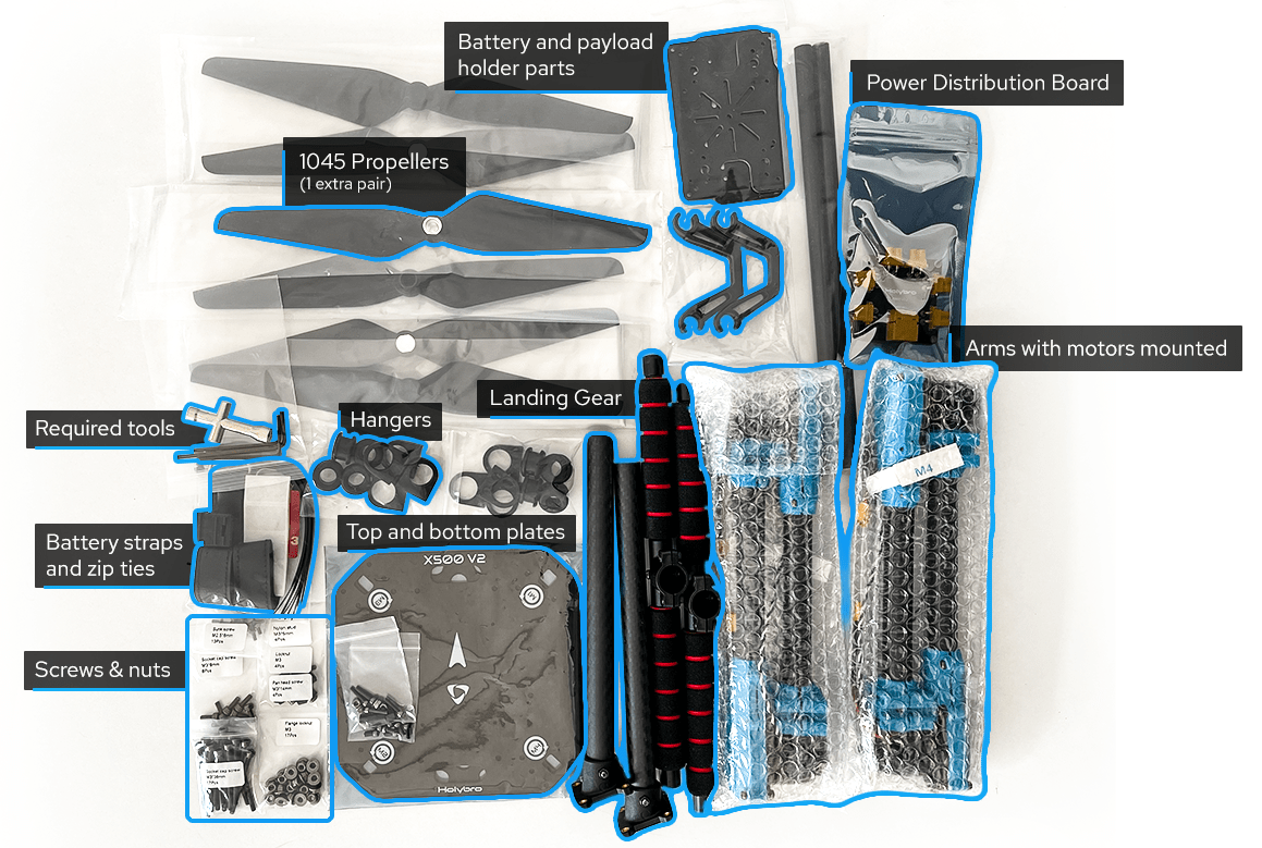
Figure 1: X500 V2 ARF Kit what's inside
# Electronics
| Item Description | Quantity |
|---|---|
| Pixhawk5x & Assorted Cables | 1 |
| M8N GPS Module | 1 |
| Power Module PM02D (with pre-soldered ESC power cables) | 1 |
| Motors 2216 KV880(V2 Update) | 4 |
| Holybro BLHeli S ESC 20A x4 | 1 |
| 433MHz Telemetry Radio / 915MHz Telemetry Radio | 1 |
# Tools needed
Tools are included to do the assembly, however you may need:
- Wire cutters
- Precision tweezers
# Assembly
Estimate time to assemble is 55 min (25 minutes for frame, 30 minutes for autopilot installation/configuration)
Start by assembling the payload & battery holder. Push the rubbers into grippers (Do not use sharp items to push them in!). Next, pass the holders through the holder bars with the battery holder bases as Figure 3.
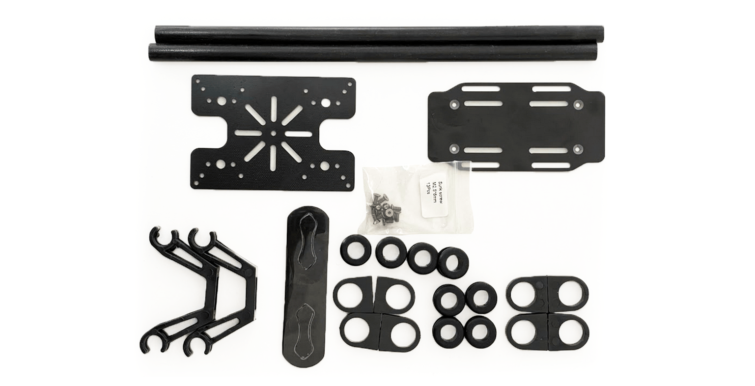
Figure 2: Payload holder components
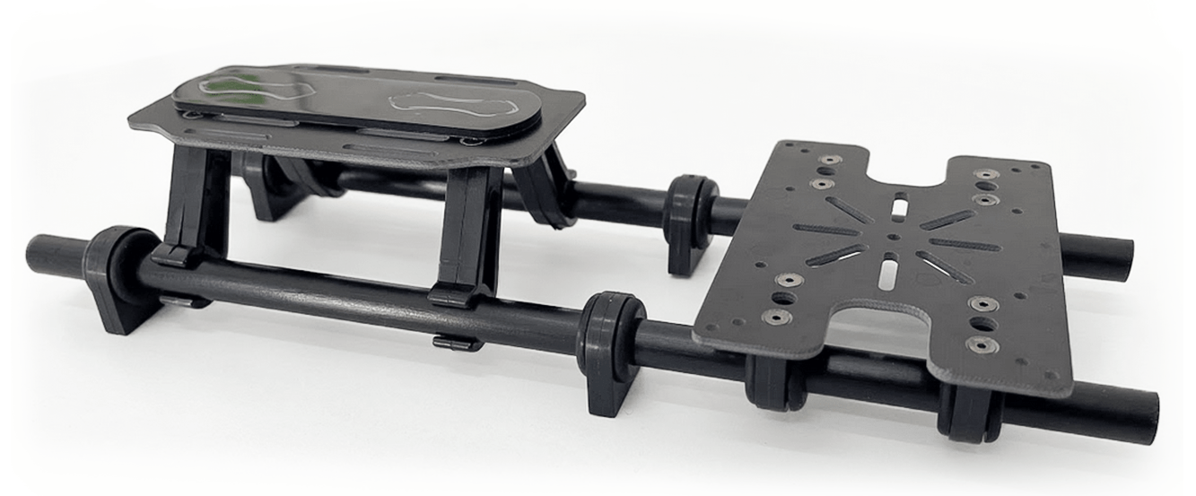
Figure 3: Payload holder assembled
The next is to go for attaching the bottom plate to the payload holder.
You will need the parts as shown in Figure 4. Then mount the base for power distribution board using nylon nuts as Figure 5. Finally using 8 hex screws you can join the bottom plate to the payload holder (Figure 7)
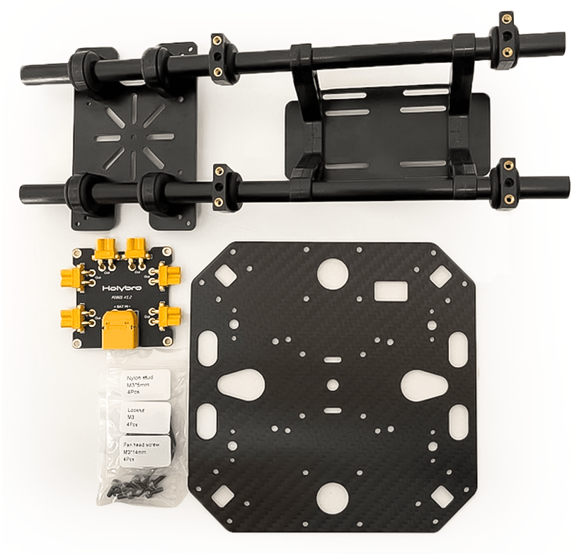
Figure 4: Needed Materials
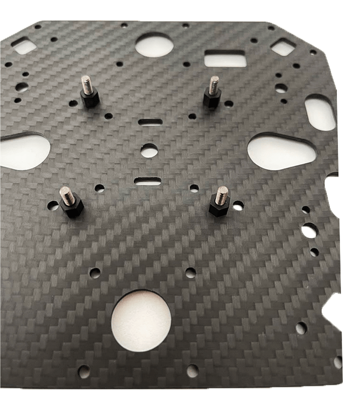
Figure 5: PDB mount base
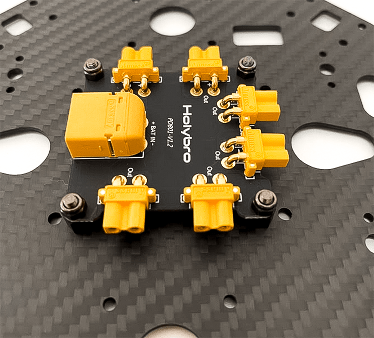
Figure 6: Mounted pdb with nylon nuts
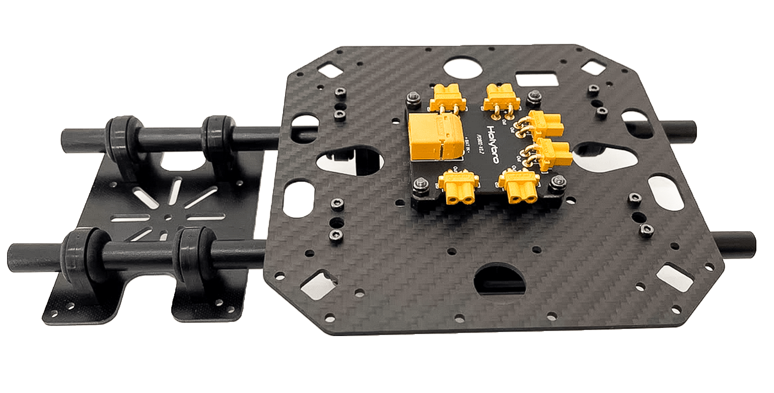
Figure 7: Mounted Plate on payload holder
Let's gather the stuff needed for mounting landing gear as Figure 8. Use the hex screws to join landing gears to the bottom plate. You also need to open three hex screws on each of the leg stands so you can push them into carbon fiber pipes. Do not forget to tighten them back again.
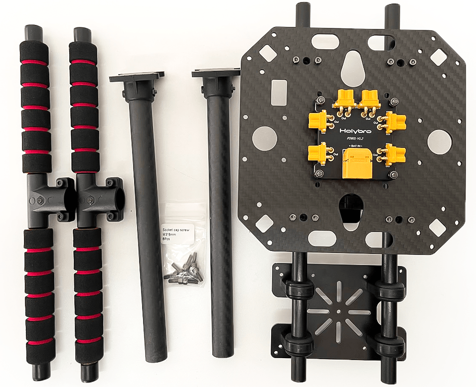
Figure 8: Required parts for landing gear attachment
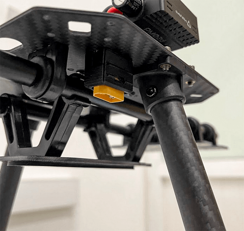
Figure 9: Landing gear attachment to the body
We will gather all the arms now to mount the top plate. Please pay attention that the motor numbers on arms are a match with the ones mentioned on the top plate. Fortunately, motors are mounted and ESCs have been connected in advance. Start by passing through all the screws as you have the arms fixed in their own places (They have a guide as shown in Figure 11 to ensure they are in place) and tighten all nylon nuts a bit. Then you can connect XT30 power connectors to the power board. Please keep in mind that the signal wires have to be passed through the top plate such that we can connect them later to Pixhawk.

Figure 10: Connecting arms needed materials.

Figure 11: Guide for the arms mount
Tighten all 16 screws and nuts by using both hex wrench and nut driver.
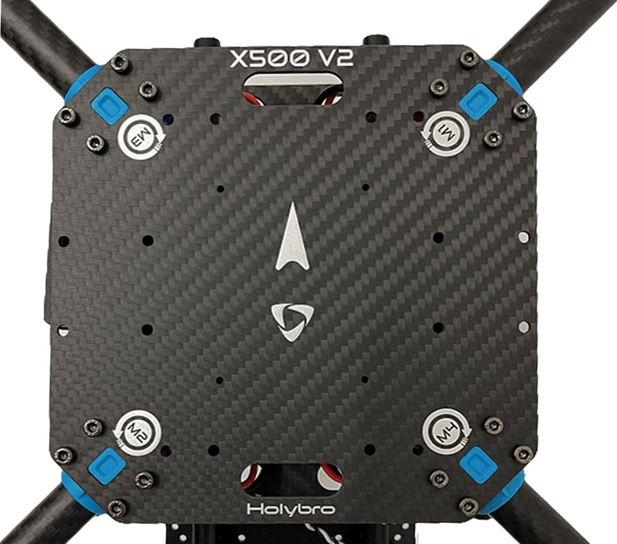
Figure 12: Mounted top plate
Next you can mount your pixhawk on the top plate by using the stickers. It is recommended to have the direction of your Pixhawk's arrow the same as the one mentioned on the top plate.
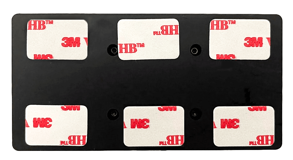
Figure 13: Sticker tapes on Pixhawk
If you want to mount the GPS on the companion computer plate, you can now secure the GPS mount onto it using 4 screws and nuts.

Figure 14: Secure GPS mount onto companion plate
Use the tape and stick the GPS to the top of the GPS mast and mount the GPS mast. Make sure the arrow on the gps is pointing forward (Figure 15).

Figure 15: GPS and mast
Finally, you can connect the Pixhawk interfaces such as telemetry radio to 'TELEM1' and motors signal cables accordingly.
Please refer to Pixhawk 5X Quick Start for more information.
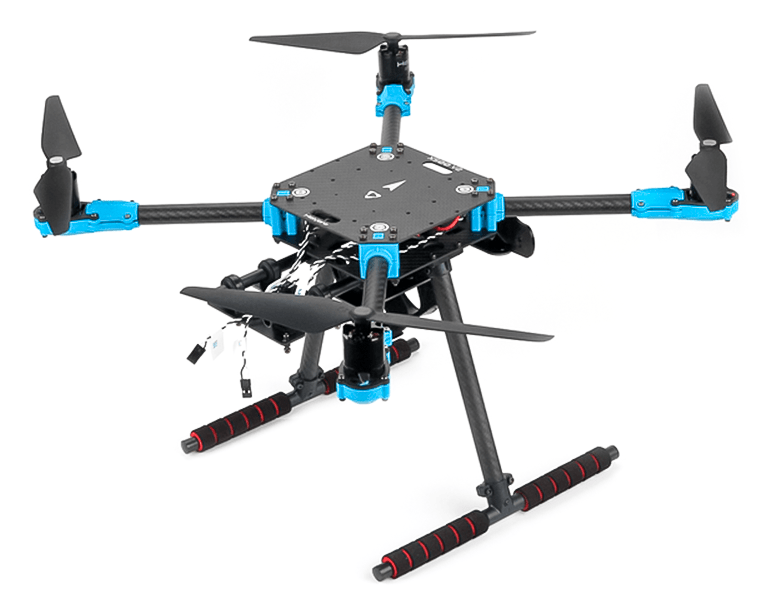
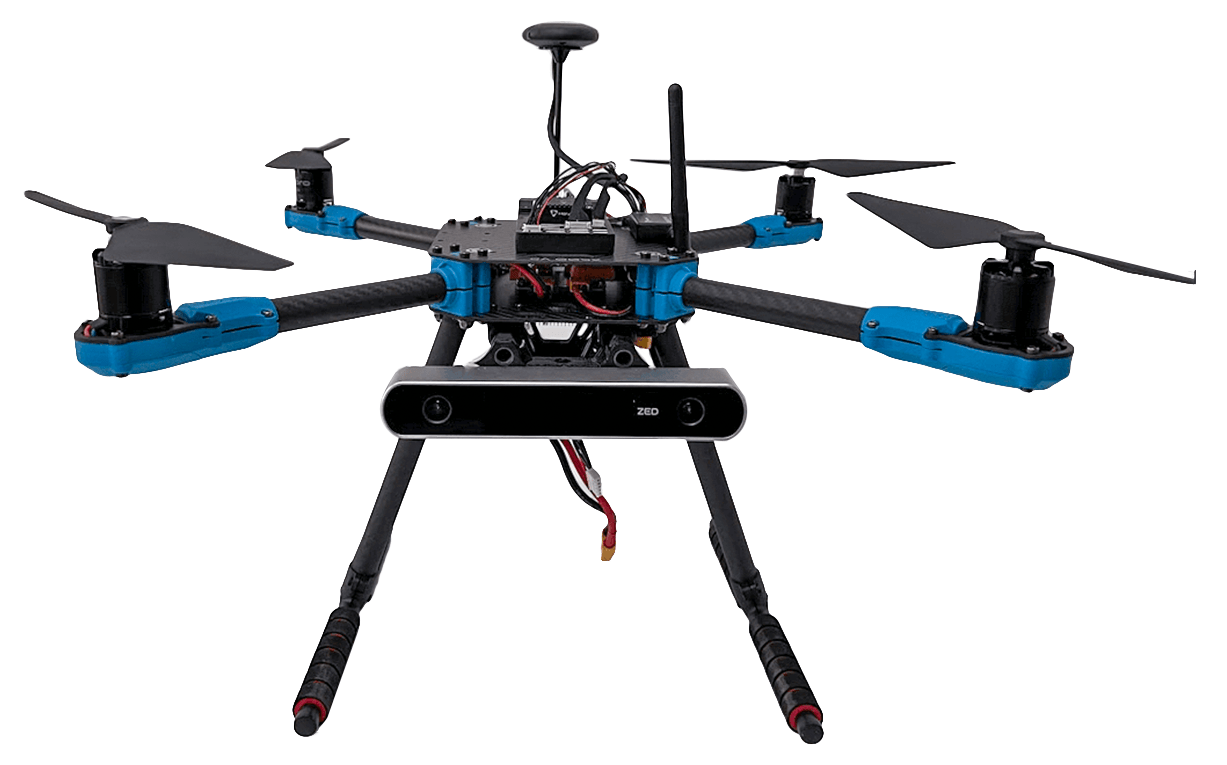
That's it. The fully assembled kit is shown below (Depth camera not included in the kit):
# Install/Configure PX4
TIP
Full instructions for installing and configuring PX4 can be found in Basic Configuration.
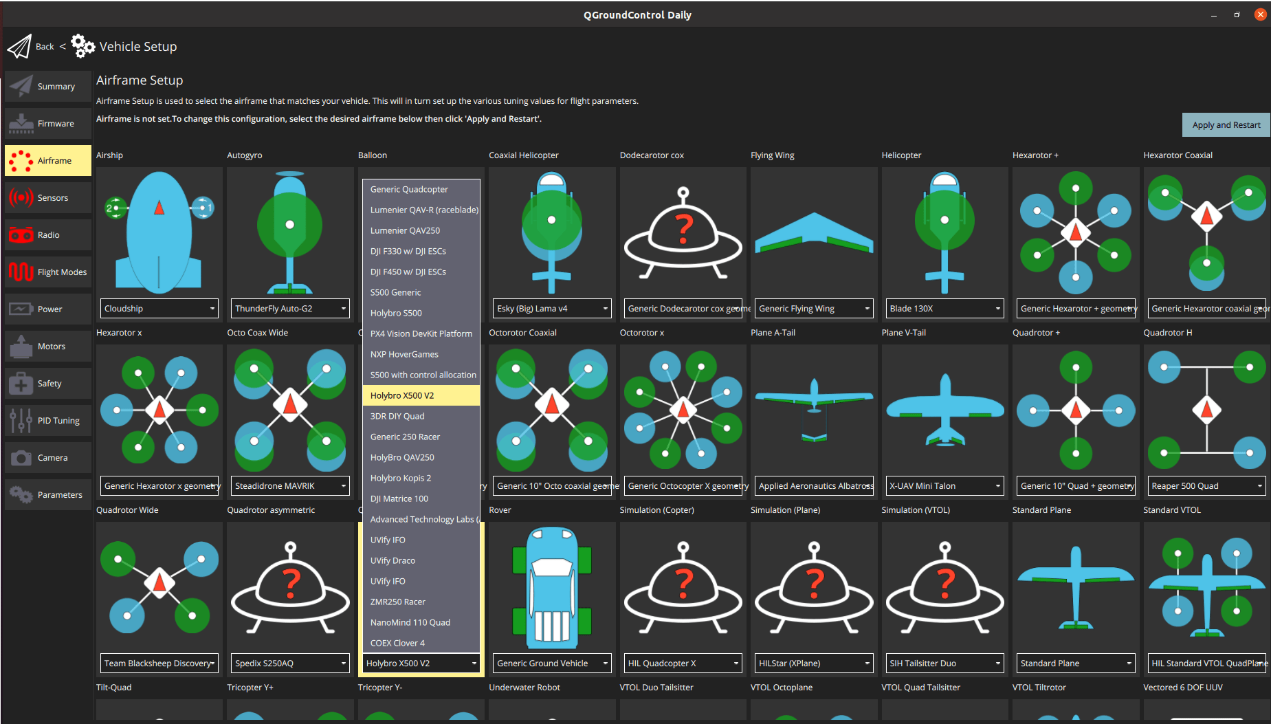
QGroundControl is used to install the PX4 autopilot and configure/tune it for the X500 frame. Download and install (opens new window) QGroundControl for your platform.
First update the firmware and airframe:
- Firmware
- Airframe - You will need to select the Holybro X500 V2 airframe (Quadrotor x > Holybro X500 V2)
Then perform the mandatory setup/calibration:
Ideally you should also do:
# Tuning
Airframe selection sets default autopilot parameters for the frame. These are good enough to fly with, but it is a good idea to tune the parameters for a specific frame build. For instructions on how, see: Multicopter Basic PID Tuning.
# Acknowledgements
This build log was provided by PX4 Team.