# Lumenier QAV250 Pixhawk Mini 조립
The Lumenier QAV250 Mini FPV Quadcopter (opens new window) is a small but fully functional FPV multicopter frame. This topic provides full build and configuration instructions for using the frame with the Pixhawk Mini flight controller, including how to install and configure the PX4 autopilot using QGroundControl.
주요 정보
- 프레임: Lumenier QAV250 CF
- 비행 컨트롤러: Pixhawk Mini
- Assembly time (approx.): 3.5 hours (2 for frame, 1.5 autopilot setup)
# Bill of Materials
이 조립에 사용된 부품들은 아래에 구매 링크와 함께 설명되어 있습니다. 일반적으로 제조업체에서 권장하는 비행 컨트롤러와 기체의 하드웨어를 사용하였습니다.
- 비행 컨트롤러: Holybro Pixhawk Mini
- 전원 모듈 : 3DR 10s 전원 모듈 (단종)
- ESC: Lumenier f390 with Blheli (getfpv.com (opens new window)). 모터와 함께 제공됩니다.
- Motors: Lumenier RX2204 -14 2300KV (getfpv.com (opens new window))
- 프로펠러: Lumenier 5x4.5 2 블레이드(getfpv.com (opens new window))
- Frame: Lumenier QAV250 - CF (getfpv.com (opens new window)) (Discontinued)
- Receiver: FrSSKY D4R-II (opens new window)
- Battery: Lumenier 4S 1300 mAh (getfpv.com (opens new window))
참고:
- The 4S Power Module that comes with the Pixhawk Mini can be used for the battery size above (instead of the 10S Power Module). 두 전원 모듈의 조립은 동일합니다.
- 또한 다음 ESC를 권장합니다 : Lumenier 12amp ESC w / SimonK AutoShot (2-4s N-FET) (getfpv.com (opens new window)).
# 하드웨어
프레임과 자율비행프로그램 설치를 위한 하드웨어들 입니다.
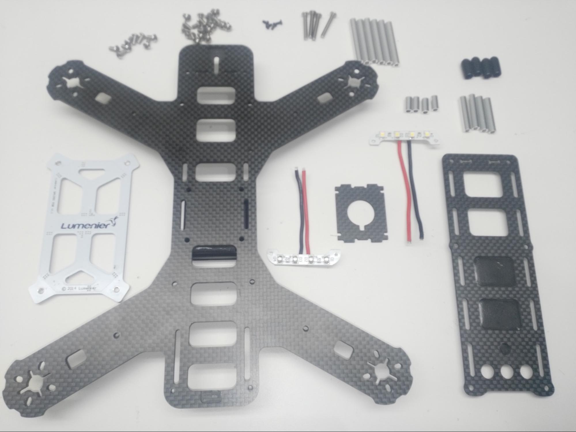
# 프레임 QAV250
| 설명 | 수량 |
|---|---|
| 유니바디 프레임 플레이트 | 1 |
| 비행 컨트롤러 커버 플레이트 | 1 |
| PDB | 1 |
| 카메라 플레이트 | 1 |
| 35mm 스탠드오프 | 6 |
| 25mm 스탠드오프 | 4 |
| 10mm 스탠드오프 | 4 |
| 비닐 캡 | 4 |
| 20mm 강철 나사 | 4 |
| 18mm 강철 나사 | 10 |
| 벨크로 배터리 혁지 | 1 |
| 배터리용 폼 | 1 |
| LED 스트립 | 2 |
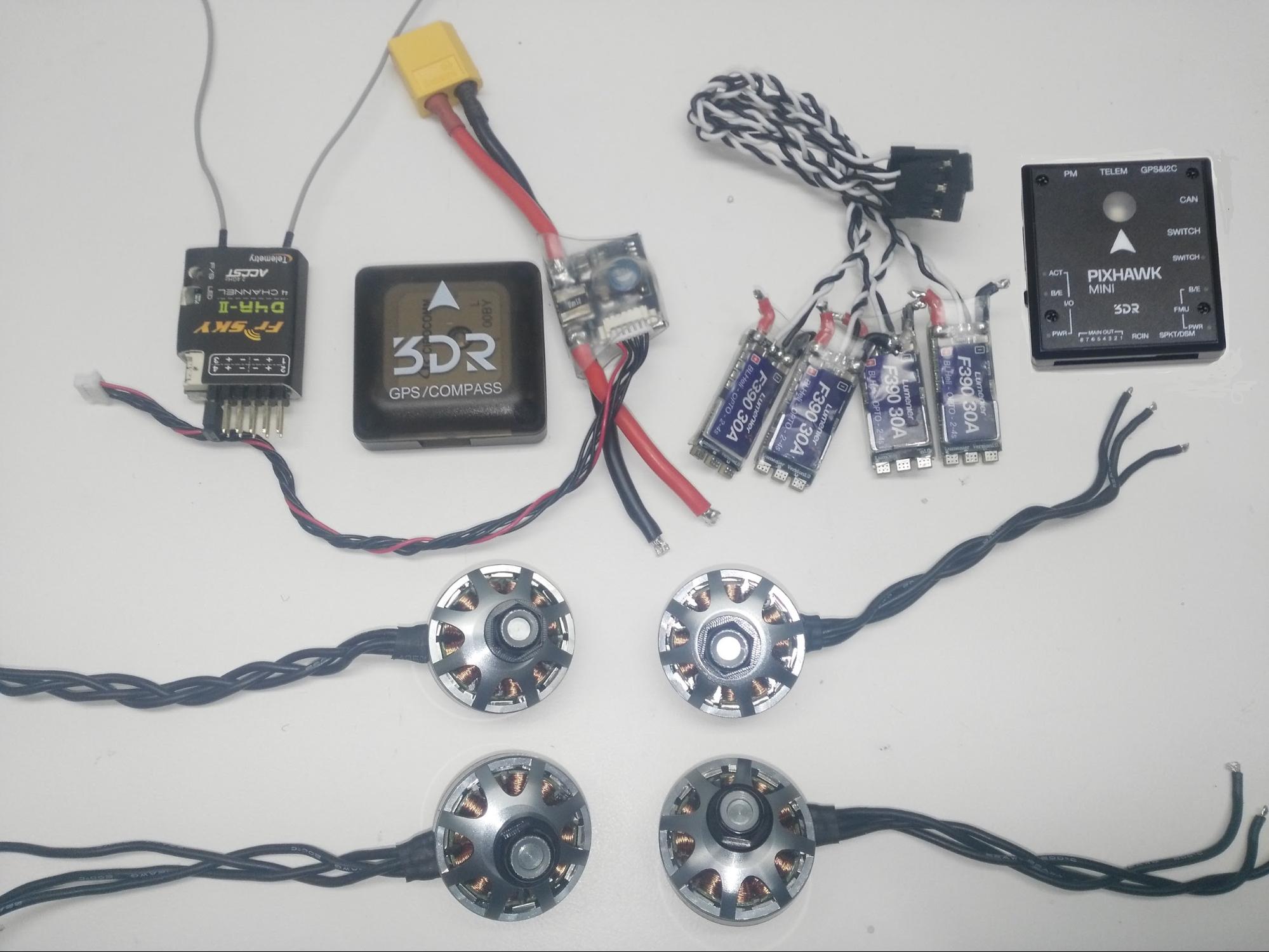
# 전자부품
| 설명 | 수량 |
|---|---|
| 모터 lumenier Rx2204-14 2300KV | 4 |
| ESC lumenier 30A | 4 |
| 3DR 전원 모듈 10S | 1 |
| Fr-sky D4R-II 수신기 | 1 |
| 3DR Pixhawk Mini autopilot | 1 |
| 3DR GPS Neo-M8N | 1 |
| 8 PWM Servo 출력 | 1 |
| 외부 안전 스위치 | 1 |
| 마이크로 SD 카드 | 1 |
| 배터리 lumenier 1300 mAh 4S 14.8V | 1 |
# 무선 텔레메트리(선택 사항)
선택사항으로, 무선텔레메트리를 사용하여 GCS (지상 관제소) 컴퓨터를 자동 조종 장치와 무선 연결할 수 있습니다. This allows you to view in-flight data, change missions on the fly, and tune in the vehicle during flight.
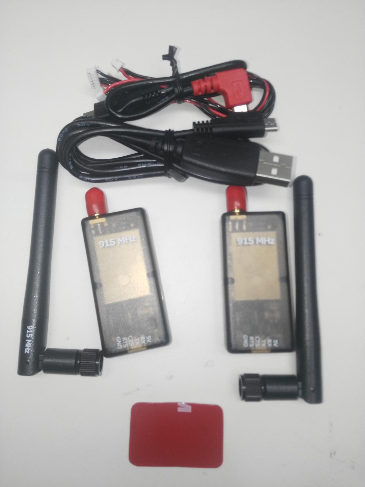
PX4/Pixhawk Mini는 다양한 무선 텔레메트리를 지원합니다. The radio used in this build is the (highly recommended) 3DR Telemetry Radio (915MHz) (Discontinued).
Note
무선 텔레메트리는 현지 규정을 적합한 적절한 주파수 대역을 사용하여야 합니다. Select a version appropriate for your region: USA - 915 MHz, Europe/Australia - 433MHz
텔레메트리 키트에는 다음과 같은 항목들이 포함되어 있습니다.
- 2 개의 텔레메트리 수신기 (차량 및 GCS 용)
- Micro USB 케이블
- Android OTG 어댑터 케이블
- 양면 테이프
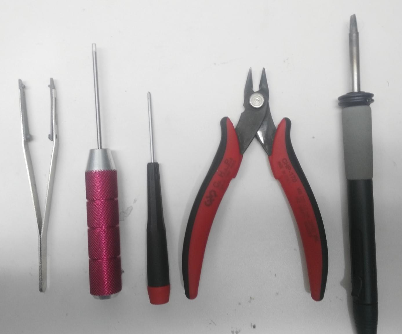
# 조립 도구
조립시에 필요한 공구들입니다.
- 2.0mm 육각 스크류드라이버
- 3mm 필립스 스크류드라이버
- 전선 커터
- 납땜 인두 및 땜납
- 정밀 트위저
# 오프-프레임 조립
이 섹션에서는 전자 장치의 배선 방법과 전자 장치없이 프레임 조립 방법을 설명합니다. 이 정보는 프레임내 스크린 샷이 명확하지 않은 경우 참고용으로 사용할 수 있습니다.
# 전자 장비 배선 / 연결 (오프 프레임)
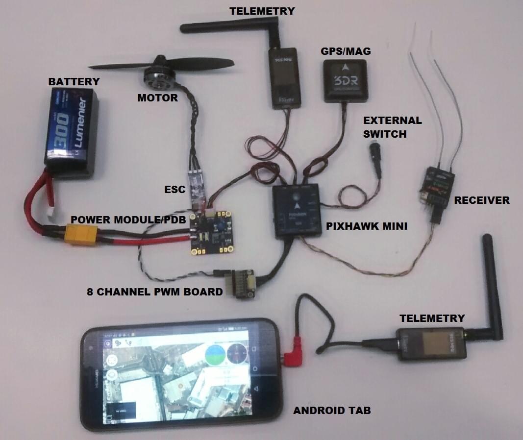
The image below shows the standard multicopter wiring for Pixhawk Mini. It uses the Quad Power Distribution Board to power the ESCs, Pixhawk and Pixhawk power rail (the board includes an integrated power module that supports batteries up to 4S).
Note
이 QAV250 빌드의 경우 대신 별도의 10S 전원 모듈을 사용하여 ESC 및 Pixhawk에 전원을 공급하고 옵션 외부 스위치를 사용하지 않습니다. The wiring is otherwise similar!
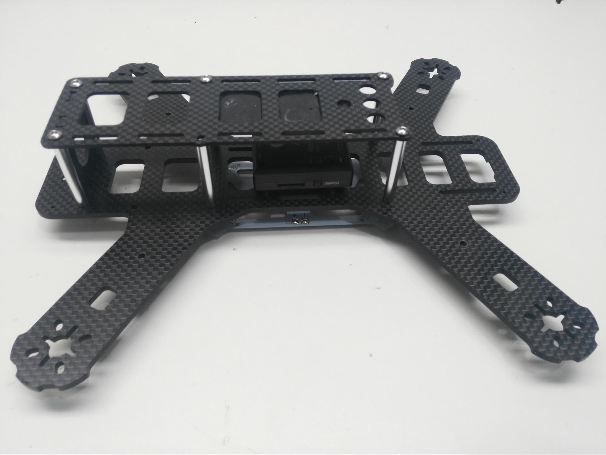
# 프레임 조립
Note
이 섹션에서는 복잡한 전자 장치를 제외한 프레임을 조립 방법을 설명합니다. 아래의 조립 문서에서 참조됩니다.
프레임 조립 방법 :
1 단계 : 그림과 같이 PDB 용 10mm 스탠드오프와 20mm 강철 나사를 사용합니다.
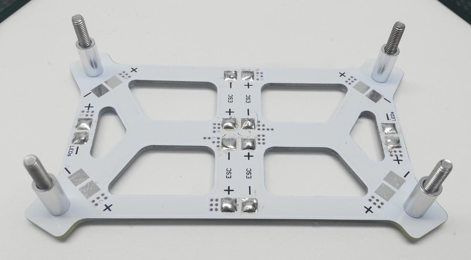
2 단계 : 스탠드오프에 프레임을 위치시킵니다.
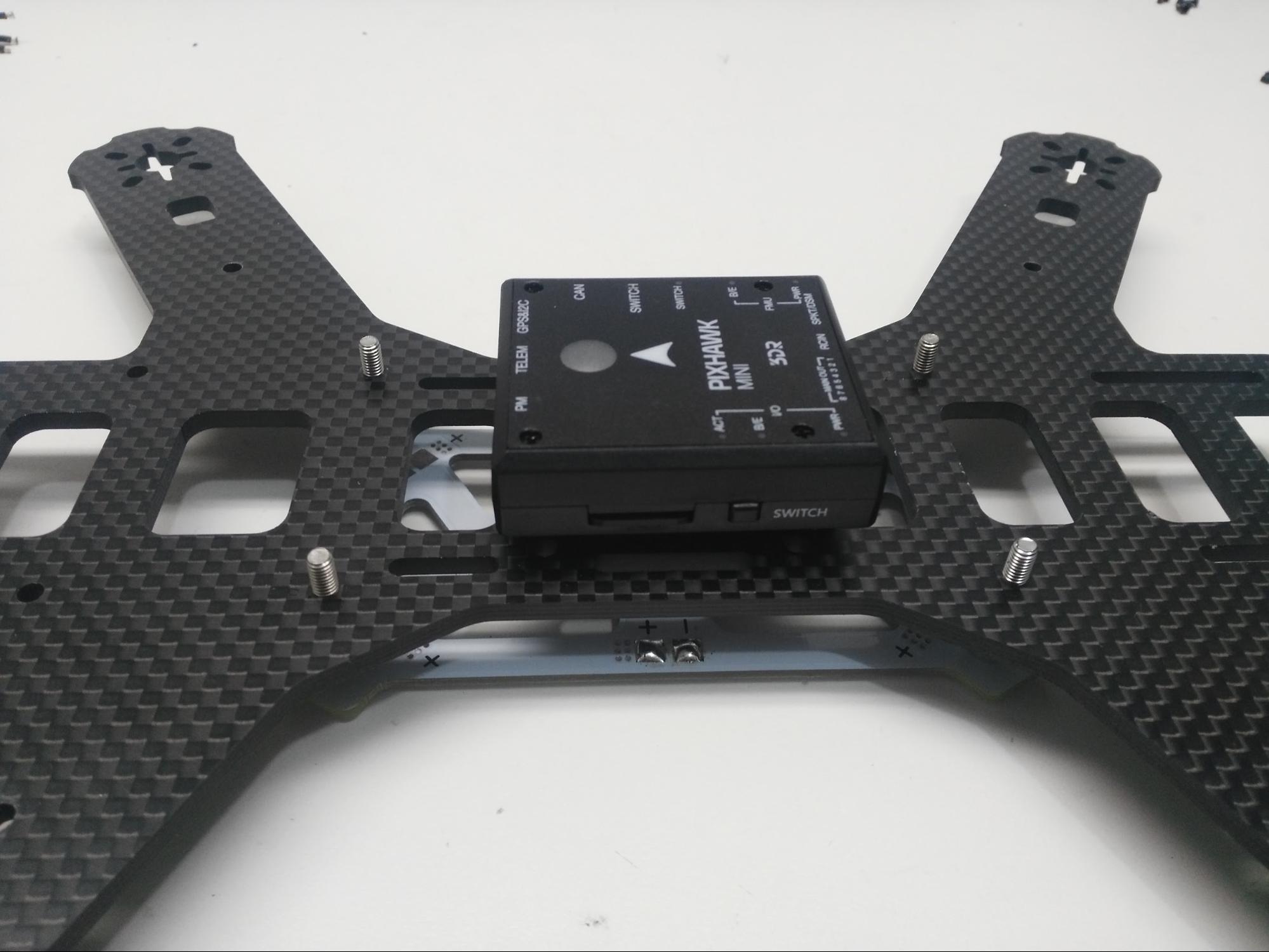
Note
프레임 플레이트가 정확하게 장착되었는 지 확인하십시오. 아래 표시된 컷은 프레임 하단을 보여줍니다. 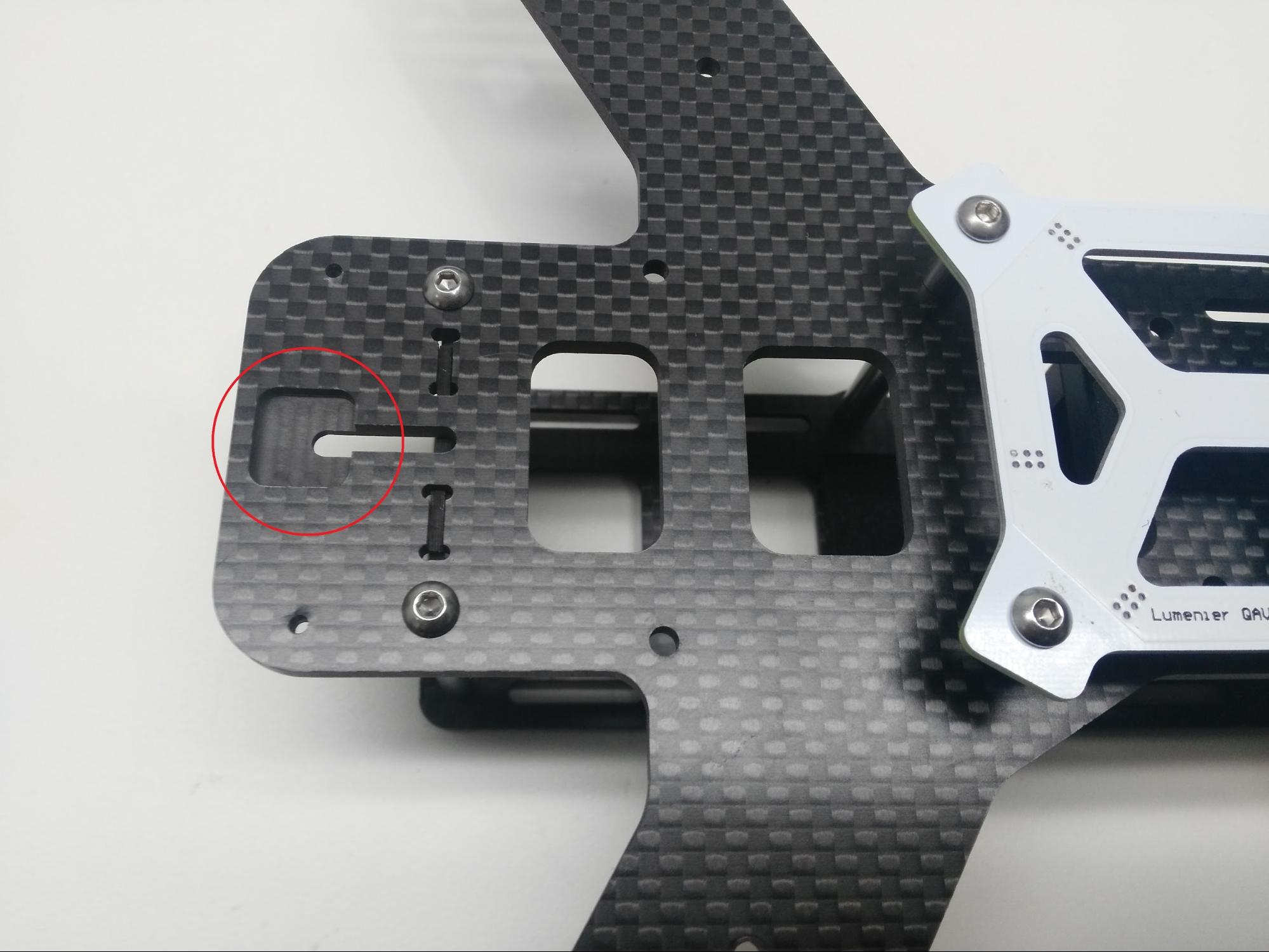 :::
:::
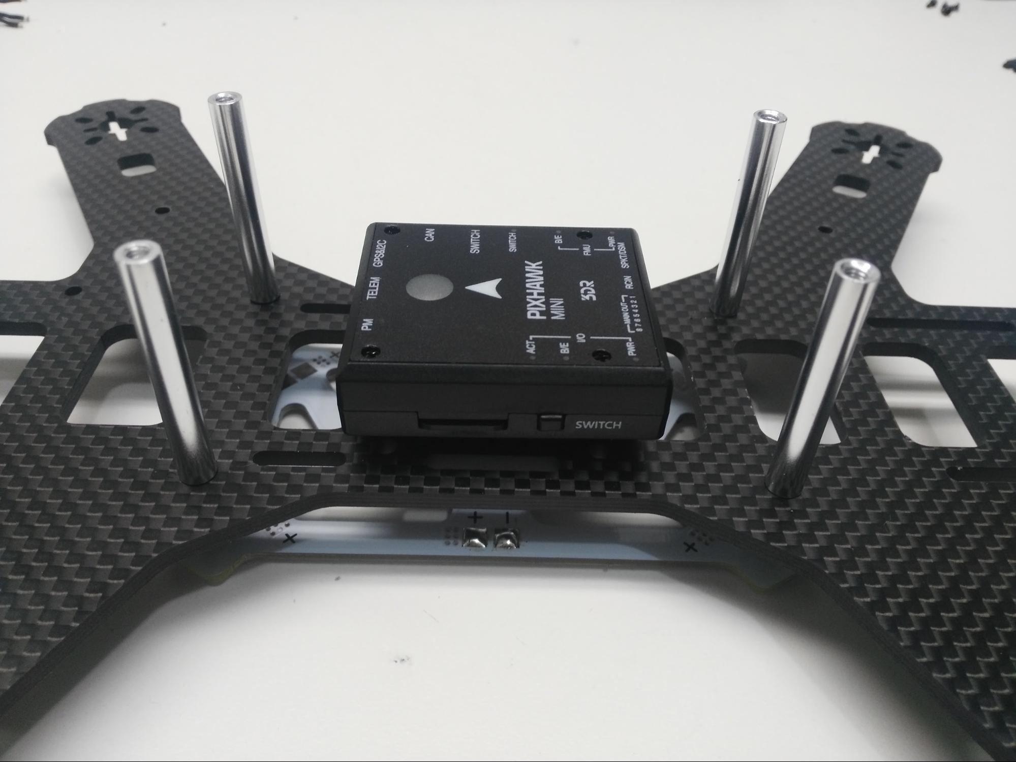
3 단계 : 나사에 35mm 스탠드오프를 끼 웁니다 (2.0mm 육각 드라이버가 필요함).
4 단계 : 카메라 플레이트를 부착하고 나머지 스탠드오프를 추가합니다.
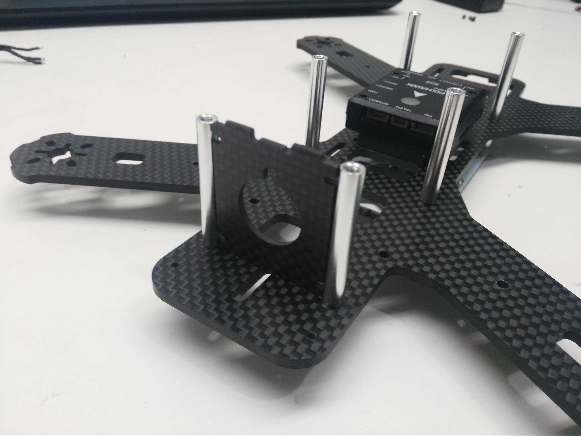
5 단계 : 비행 컨트롤러 커버 플레이트를 스탠드오프에 놓고 나사로 고정합니다.
추가: 제조업체에서 제공하는 조립 방법은 여기에서 찾을 수 있습니다. Lumenier QAV250 탄소 섬유 조립 매뉴얼 (opens new window).
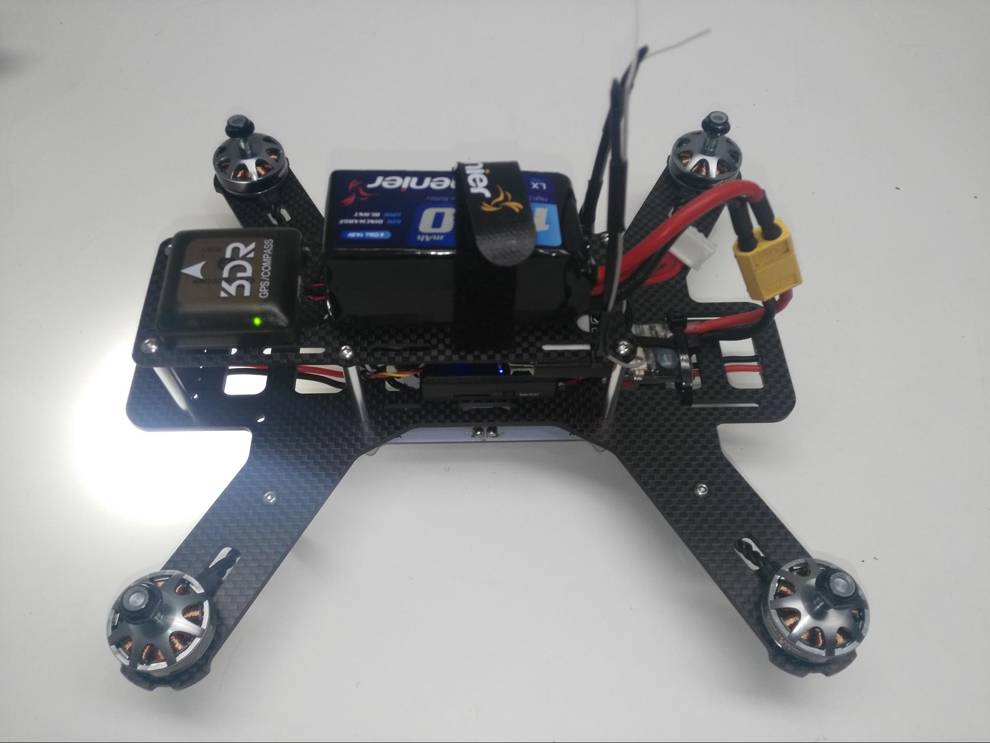
# 전자 장치를 포함한 전체 조립
Pixhawk Mini, 모터 및 기타 전자 장치와 함께 QAV250의 전체 조립 방법을 설명합니다.
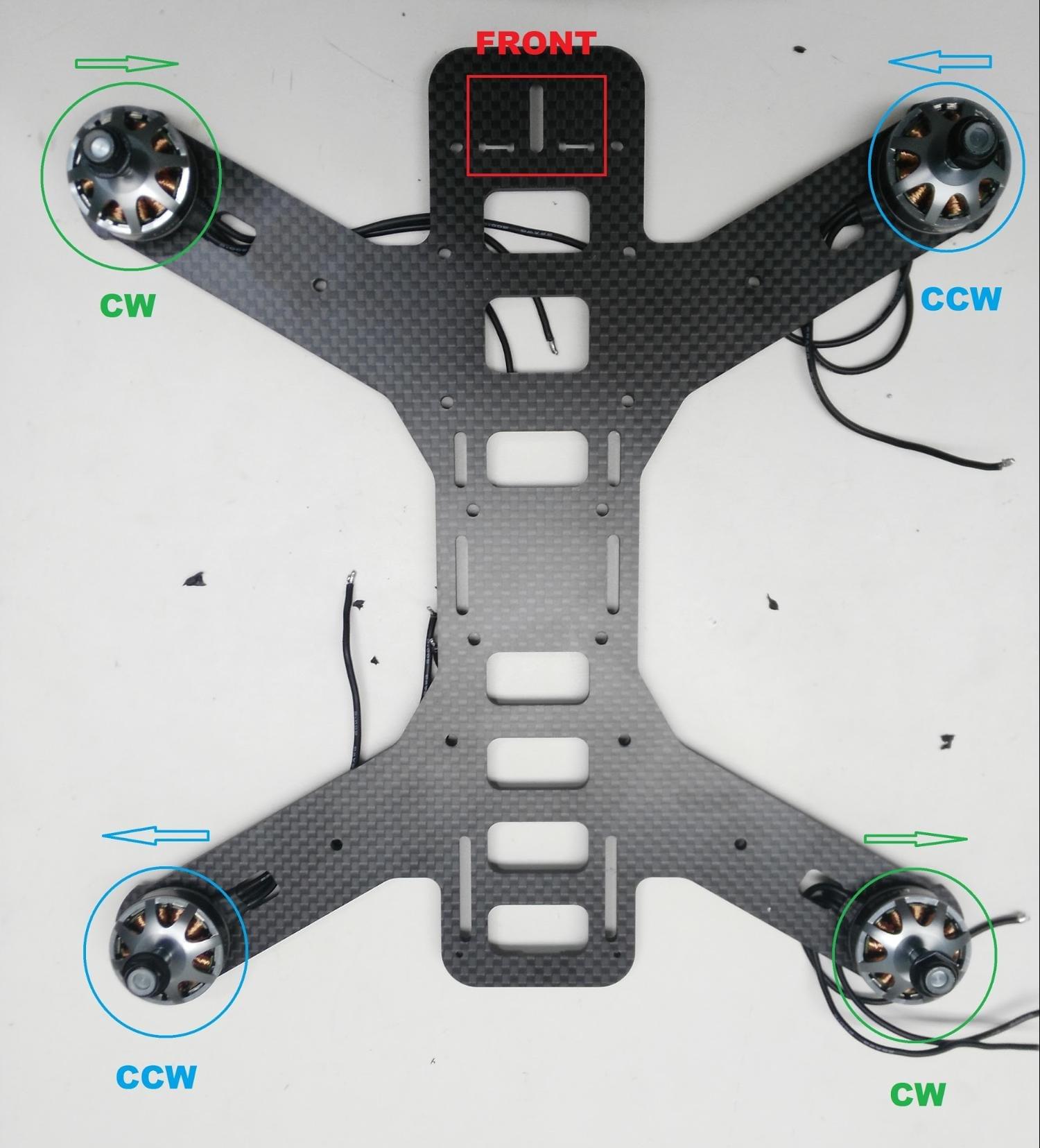
1 단계 : 모터 설치
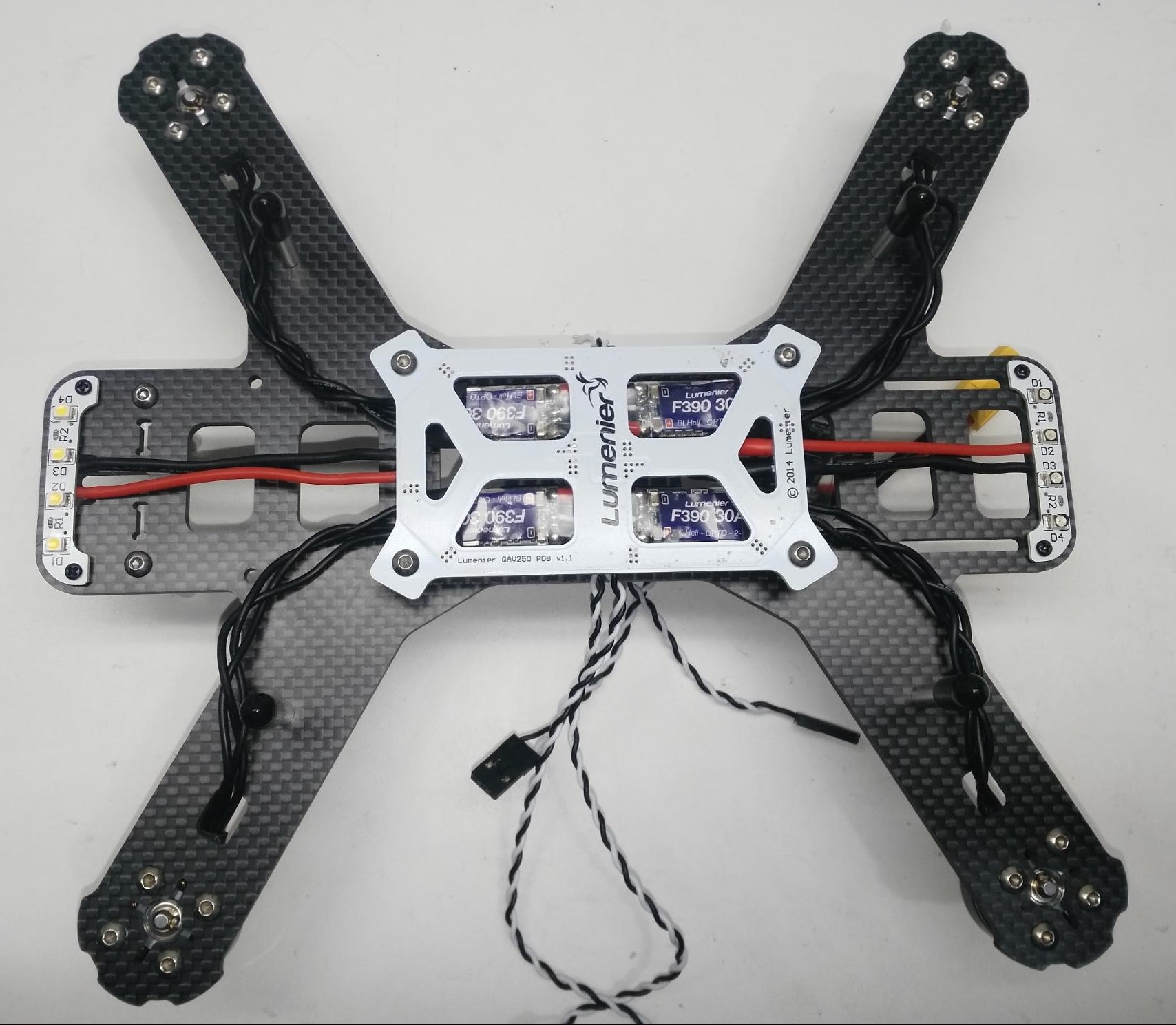
빨간색 표시는 프레임의 전방을 표시합니다. 프레임에 순서대로 모터를 배치하고 프레임 하단을 통해 케이블을 통과 시키십시오.
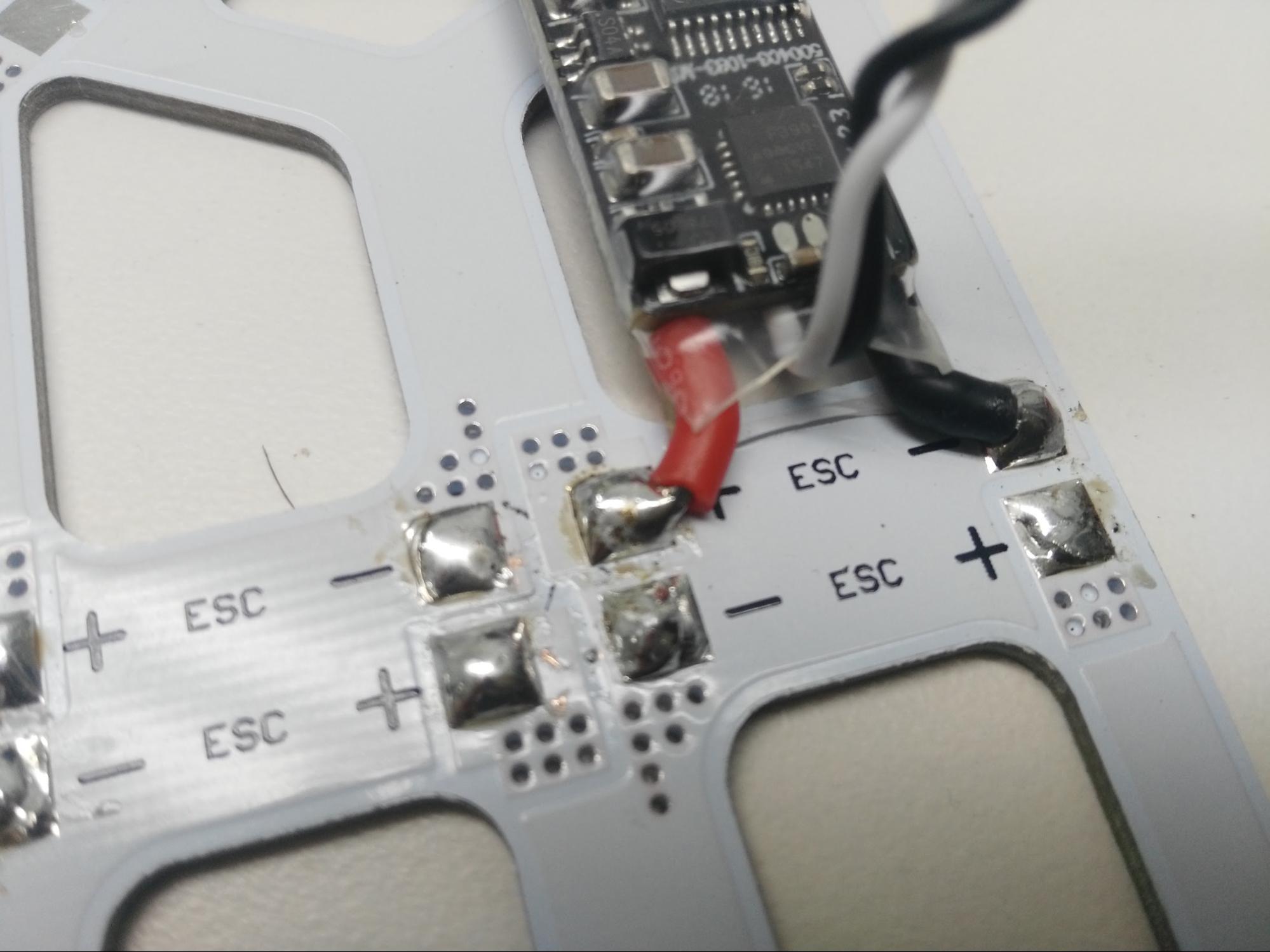
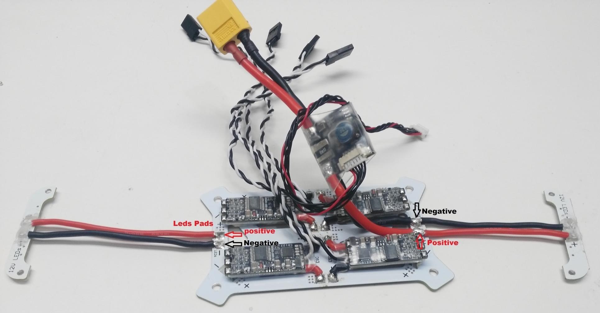
Step 2: Solder the 4 ESCs to the PDB
빨간 색 케이블은 양극 패드에 납땜하고, 검은 색 케이블은 음극 패드에 납땜하여야 합니다 (아래는 단일 ESC에 대해 표시됨).
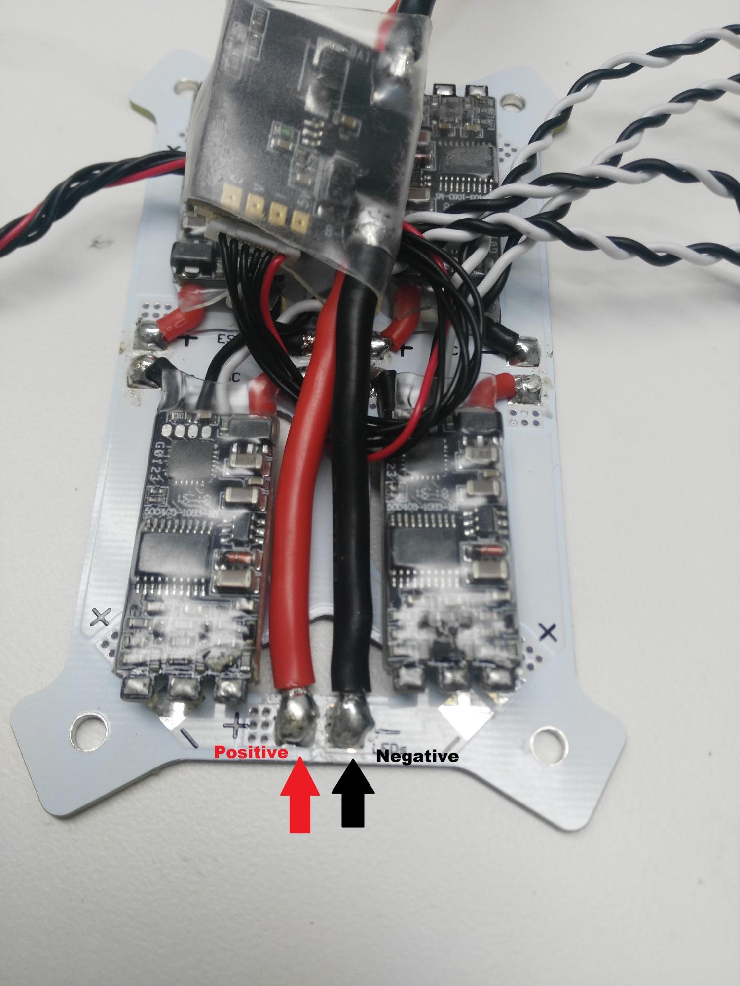
3 단계 : 전원 모듈을 PDB에 납땜
The red cable should be soldered to the positive pad and the black cable to the negative pad. 조립방법에 맞는 방식으로 납땜하십시오.
4 단계 : LED를 PDB에 납땜
Red cables should connect to the positive pad and black cables with negative pads. The white LEDs are for the front and the red LEDs are for back.
5 단계 : 모터를 ESC에 납땜
아래 그림과 같이 모터 케이블을 ESC 패드에 납땜하십시오. 모터가 올바른 방향으로 회전하는지 확인하십시오. If not, swap the positions of cables A and C on the ESC.
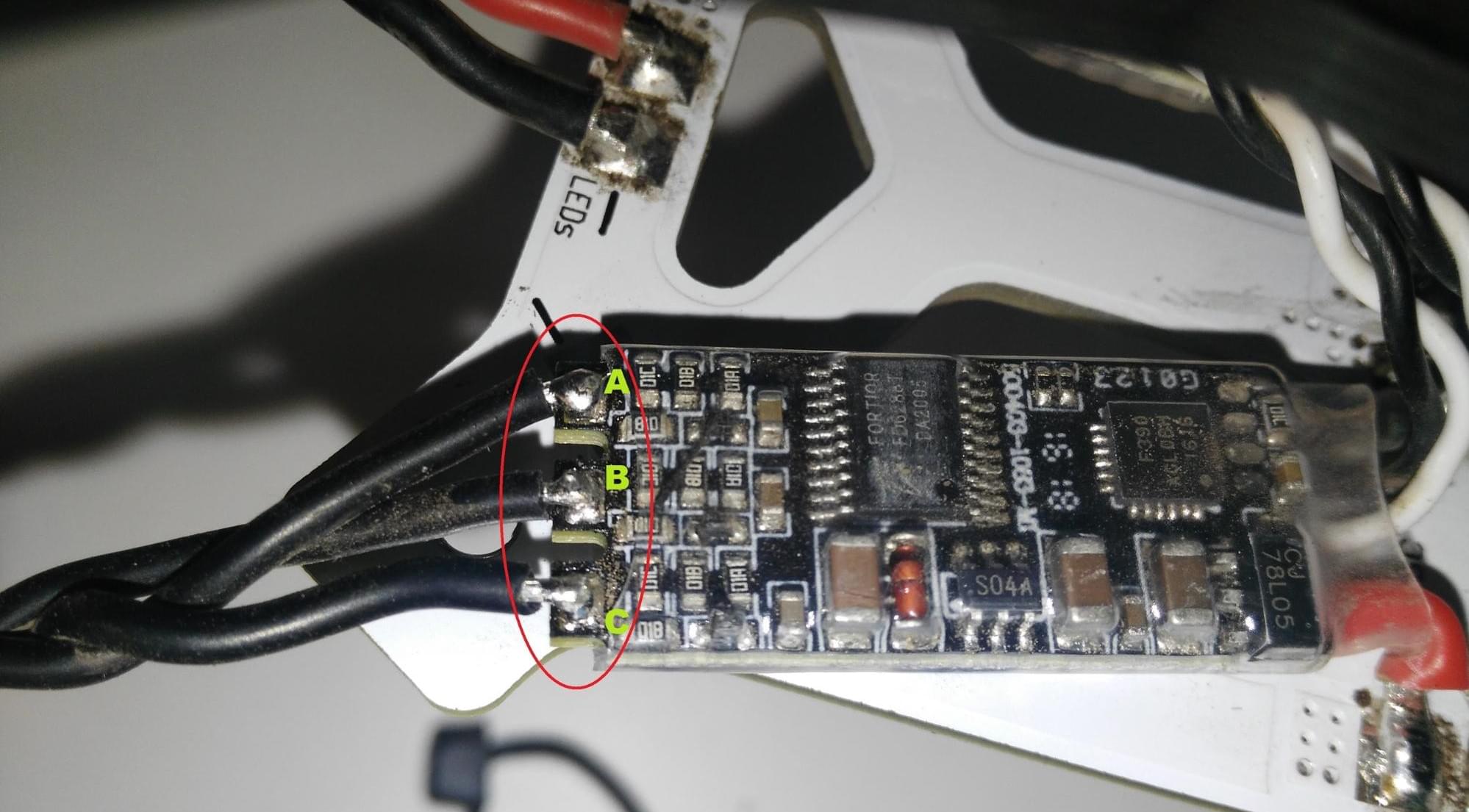
Note
케이블이 올바른 순서로 납땜되면 전기 테이프 또는 튜브로 패드를 덮으십시오. 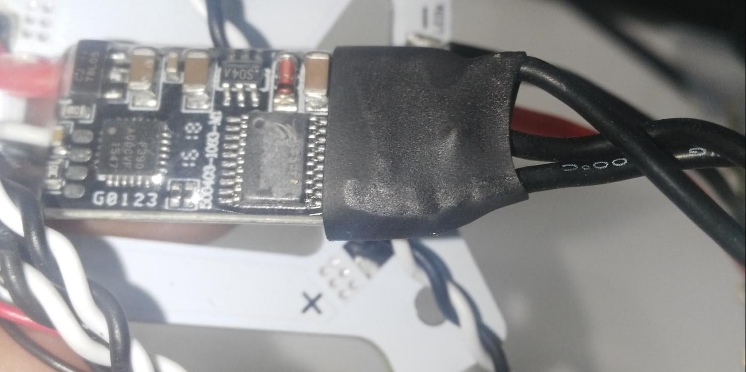 :::
:::
6 단계 : 프레임에 PDB 연결
프레임 조립 섹션에 설명된 단계를 따르십시오.
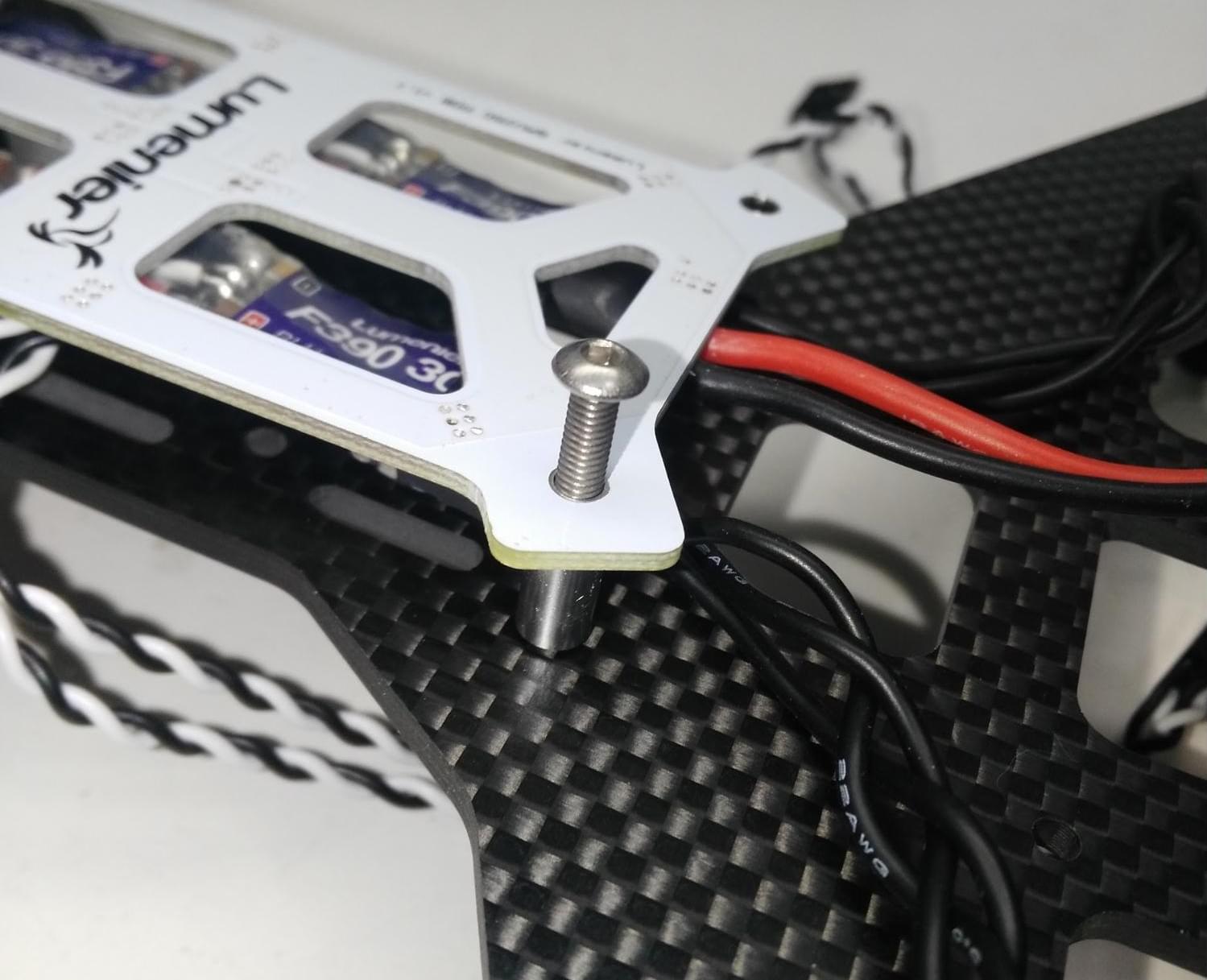
Step 7: Attach the LEDs to the frame using the Phillips screws provided.
WARNING
탄소 섬유는 프레임의 용접과의 접촉을 피하기 위해 사용되는 전도성 실리콘입니다. 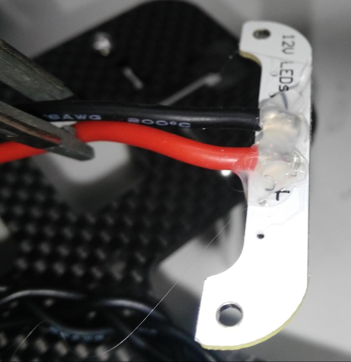 :::
:::
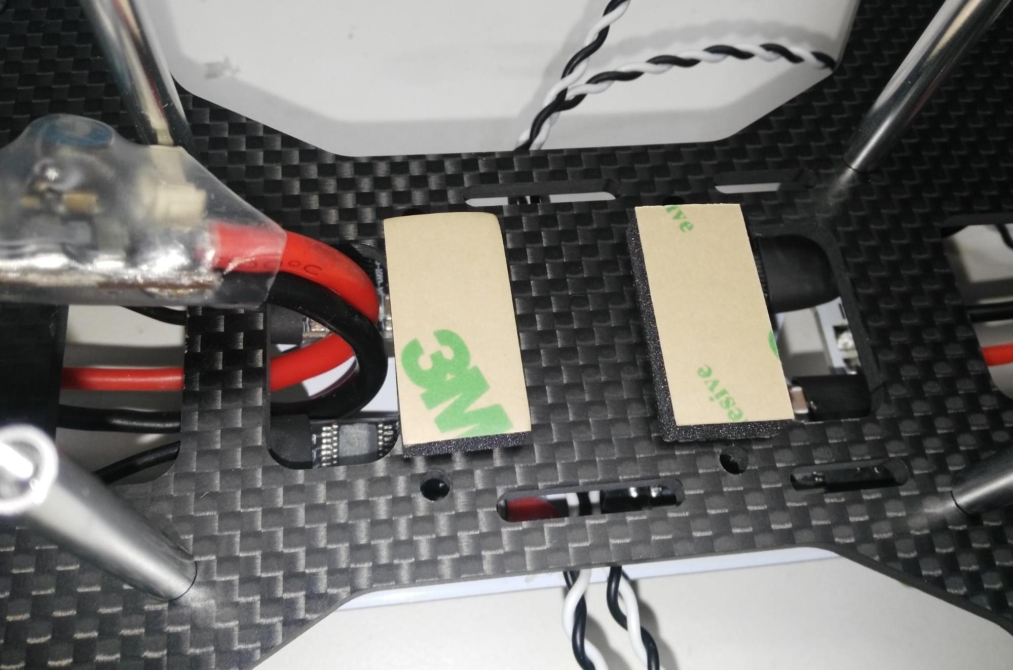
Step 8: Attach vibration damping foam to the frame as shown (the foam is included in the Pixhawk Mini kit).
폼은 Pixhawk 성능에 영향을 미칠 수 있는 진동을 줄여줍니다. 폼은 양면이 끈적끈적 합니다.
Step 9: Attach the Pixhawk Mini to the frame using the damping foam.
Pixhawk는 화살표가 프레임 전면을 향하도록 방향을 맞추어야야 합니다.
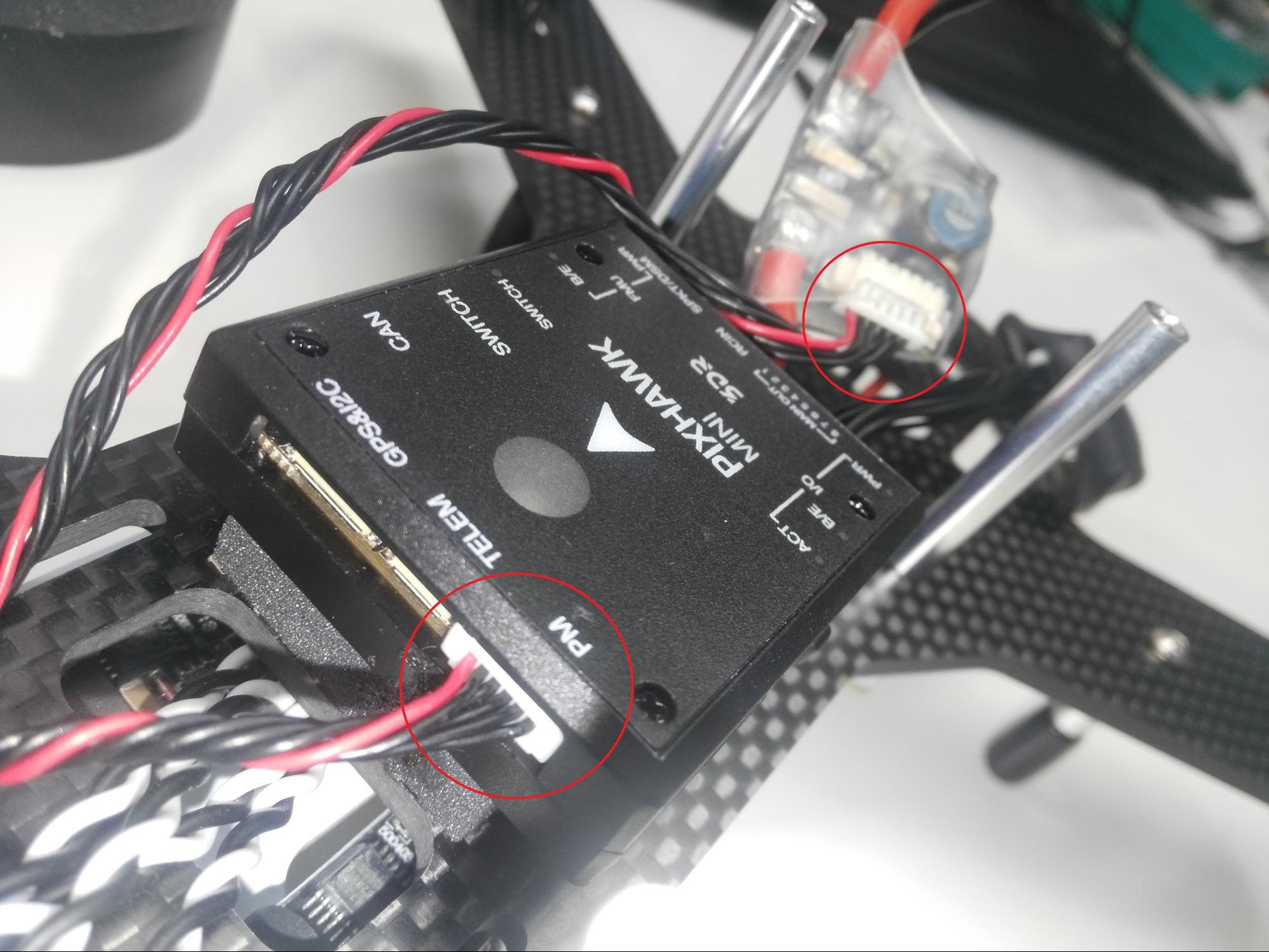
Step 10: Connect the power module.
제공된 6 핀 케이블을 사용하여 전원 모듈과 Pixhawk Mini를 연결합니다 (그림 참조). Pixhawk Mini 키트의 전원 모듈을 사용하는 경우 동일한 방법으로 연결됩니다.
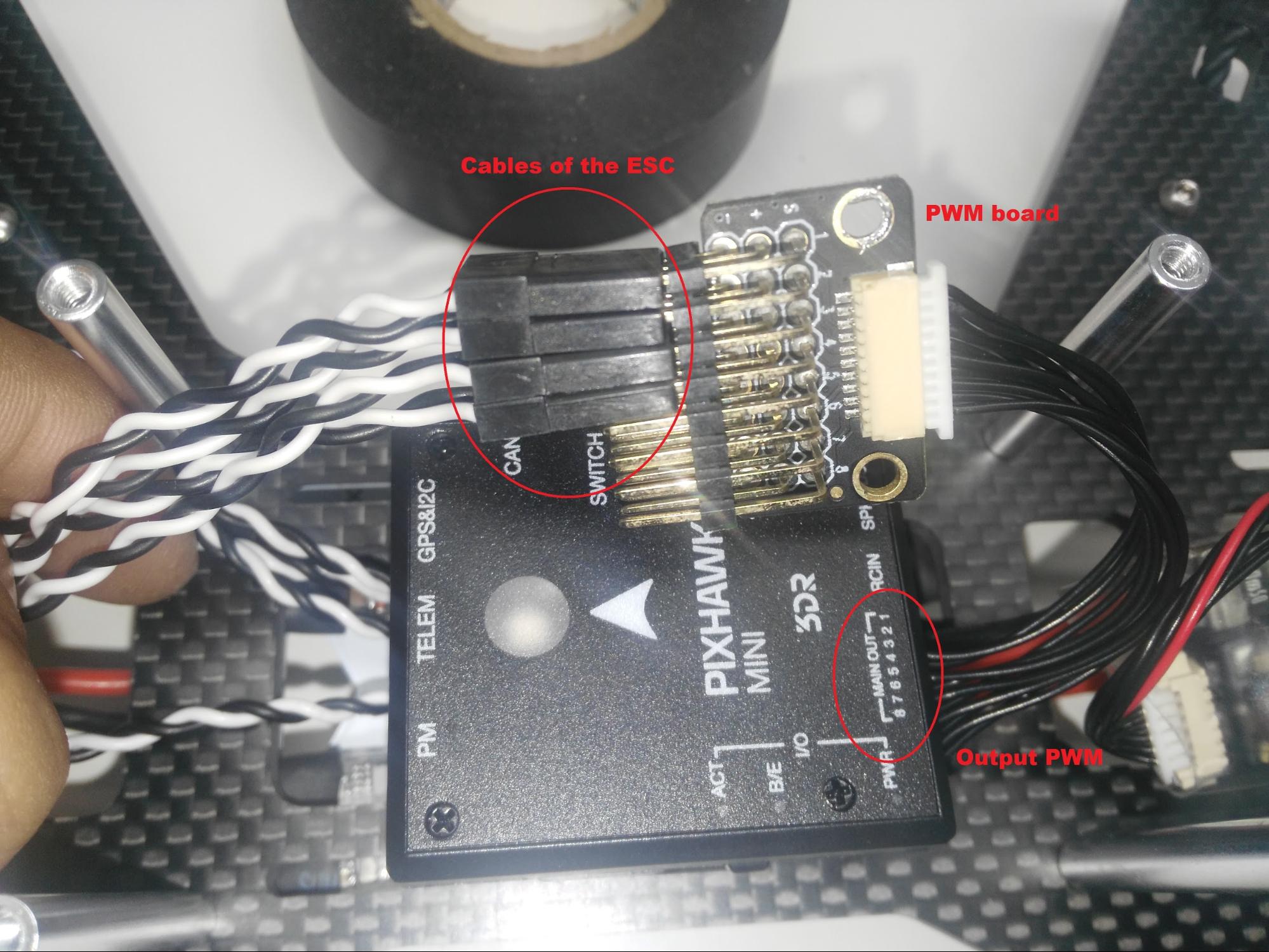
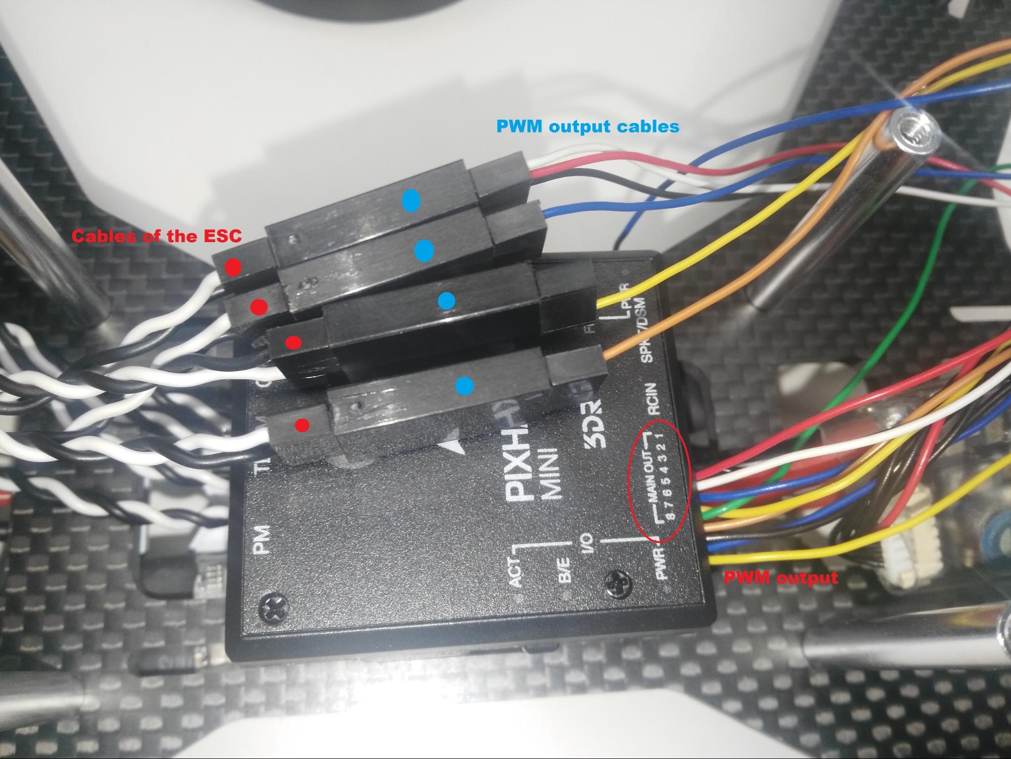
Step 11: Connect ESC to the PWM output
Attach the ESCs to the Pixhawk Mini in the correct order, using either a PWM output cable or a PWM board as shown below (both are supplied in the Pixhawk Mini kit ).
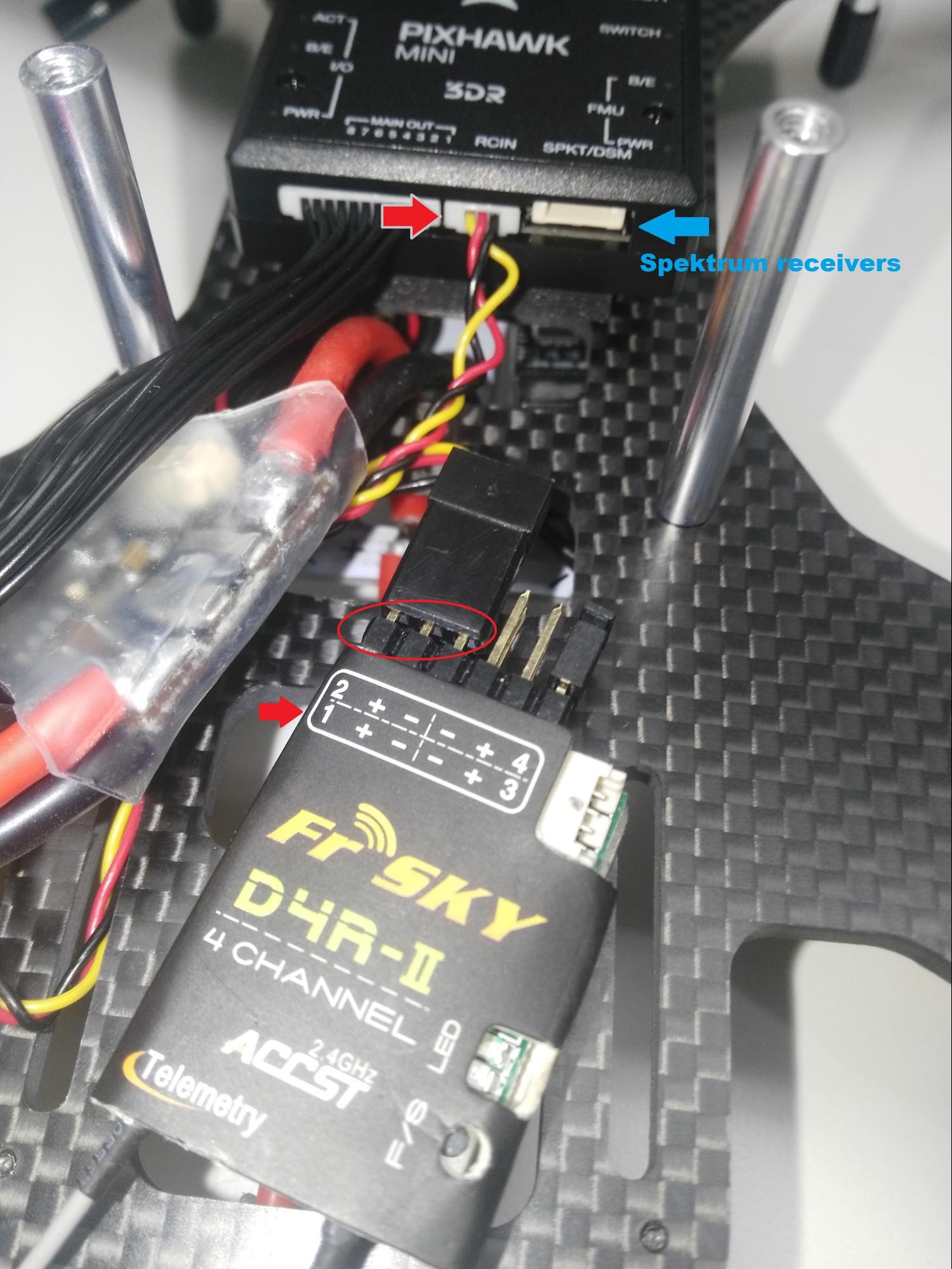
Step 12: Connect the receiver
Connect the FRSky D4-R receiver channel 1 to the RCIN port on the Pixhawk Mini (as shown).
Note
수신기에 대한 참고 사항 :
- The Pixhawk Mini RCIN port accepts PPM input (i.e. multiplexed channels). PWM 수신기 (각 채널에 대한 개별 케이블 포함)를 사용할 수 있지만, 이와 같은 (opens new window) PPM 인코더를 통해 연결해야합니다.
- You can also use a Spektrum receiver. Pixhawk Mini의 RCIN 옆에있는 SPKT/DSM 입력에 연결됩니다.
- For more information see: Pixhawk Mini Receiver Compatibility :::
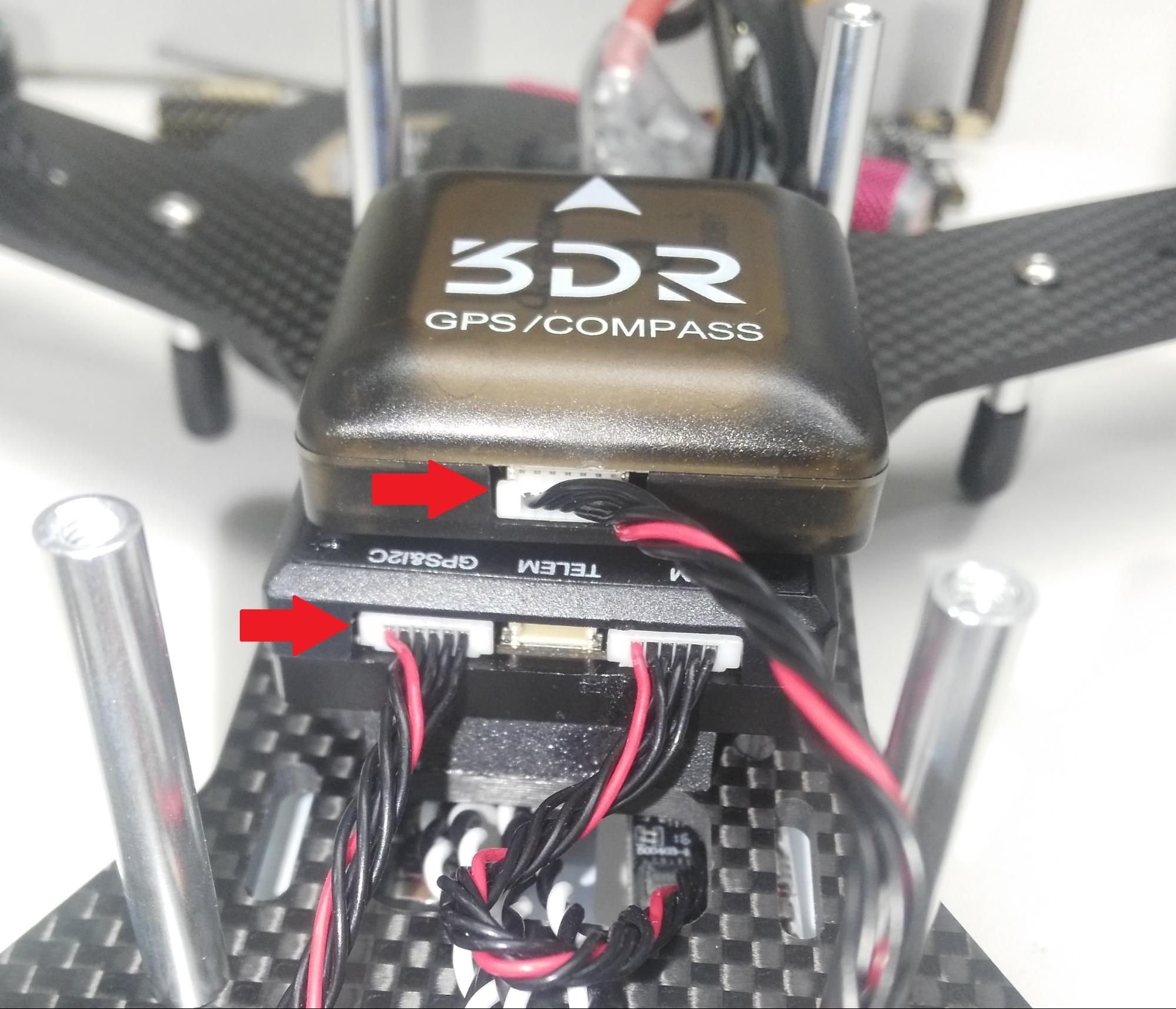
Step 13: Connect the GPS/COMPASS module
Connect the GPS/COMPASS module to the Pixhawk Mini's GPS&I2C port as shown below.
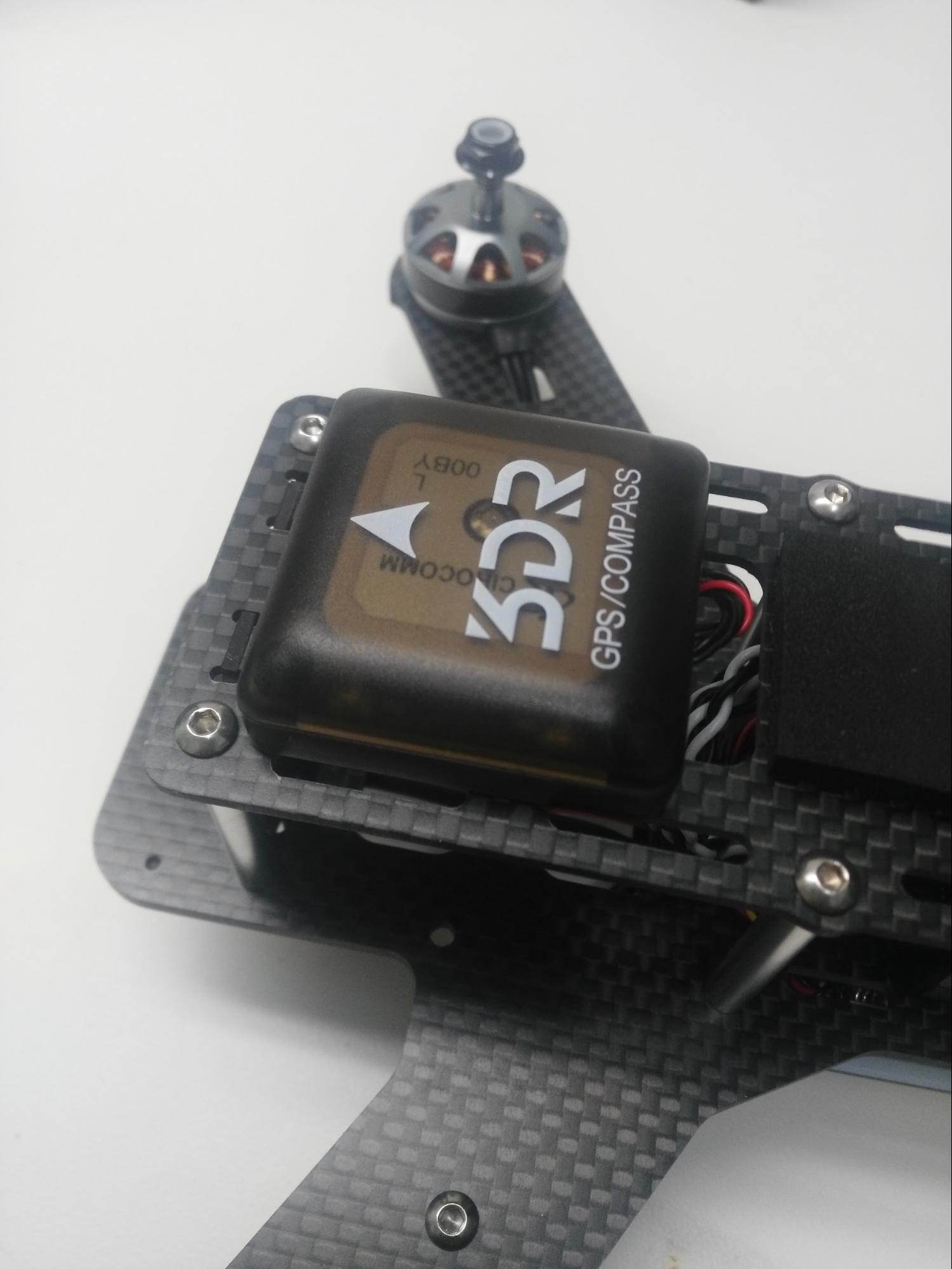
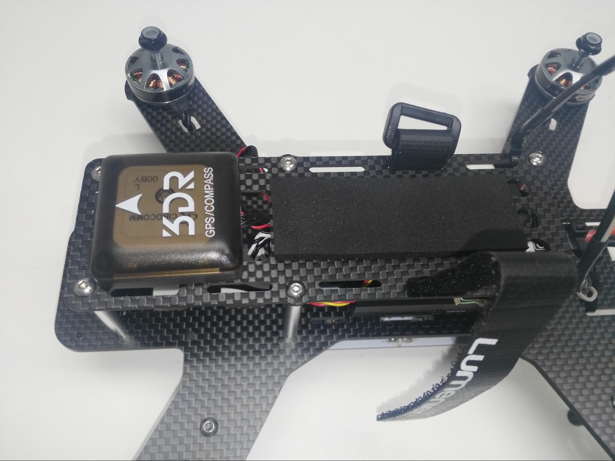
Step 14: Mount the GPS/COMPASS module
Attach flight controller cover plate (see frame assembly instructions) and then paste the GPS module onto the cover plate with the arrow to the front (paste included in kit).
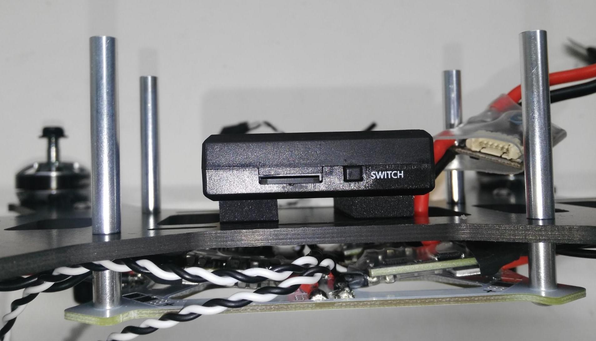
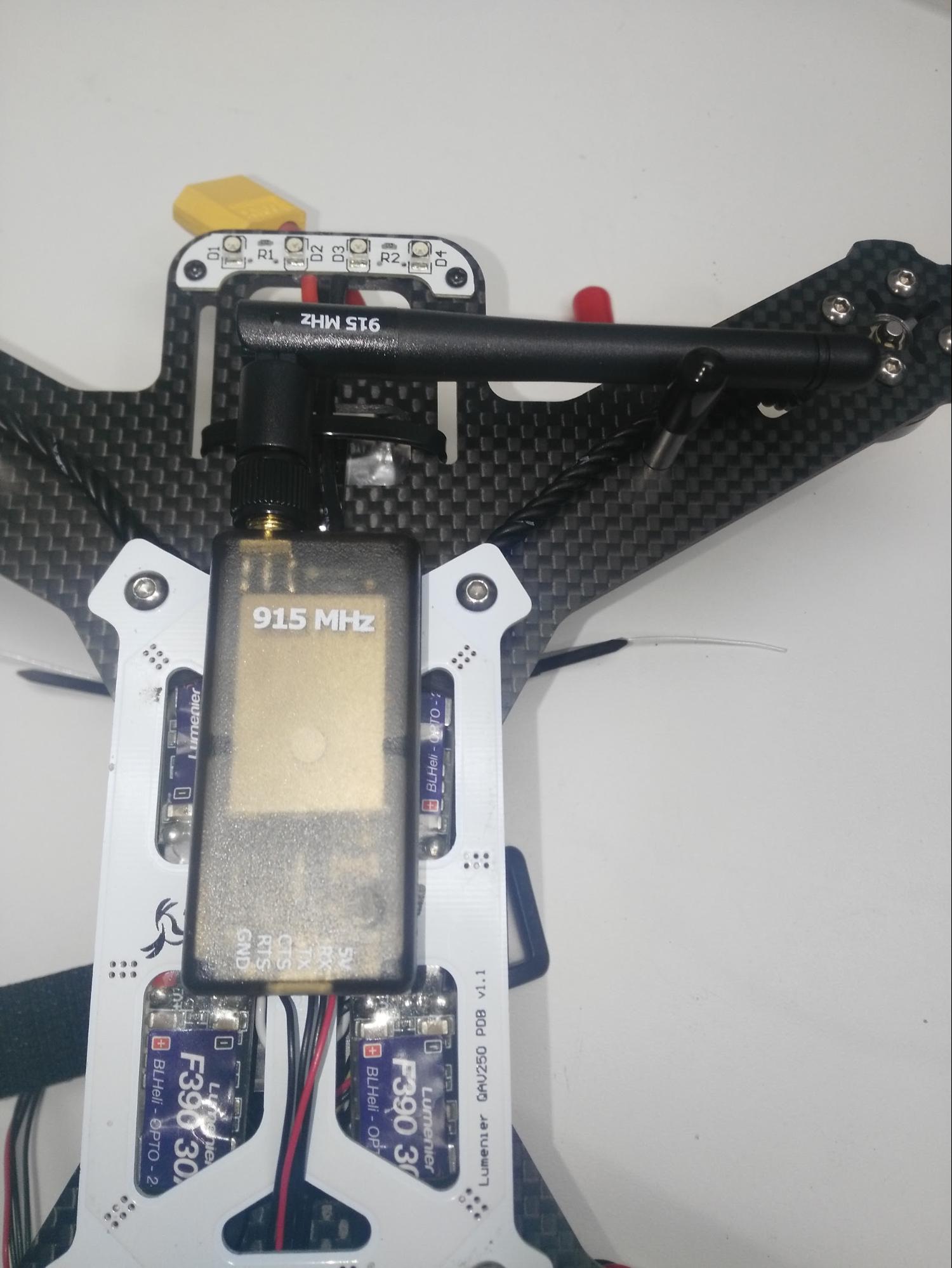
Step 15: Connect and mount the telemetry radio (Optional)
Connect the telemetry radio to the Pixhawk Mini TELEM port as shown.
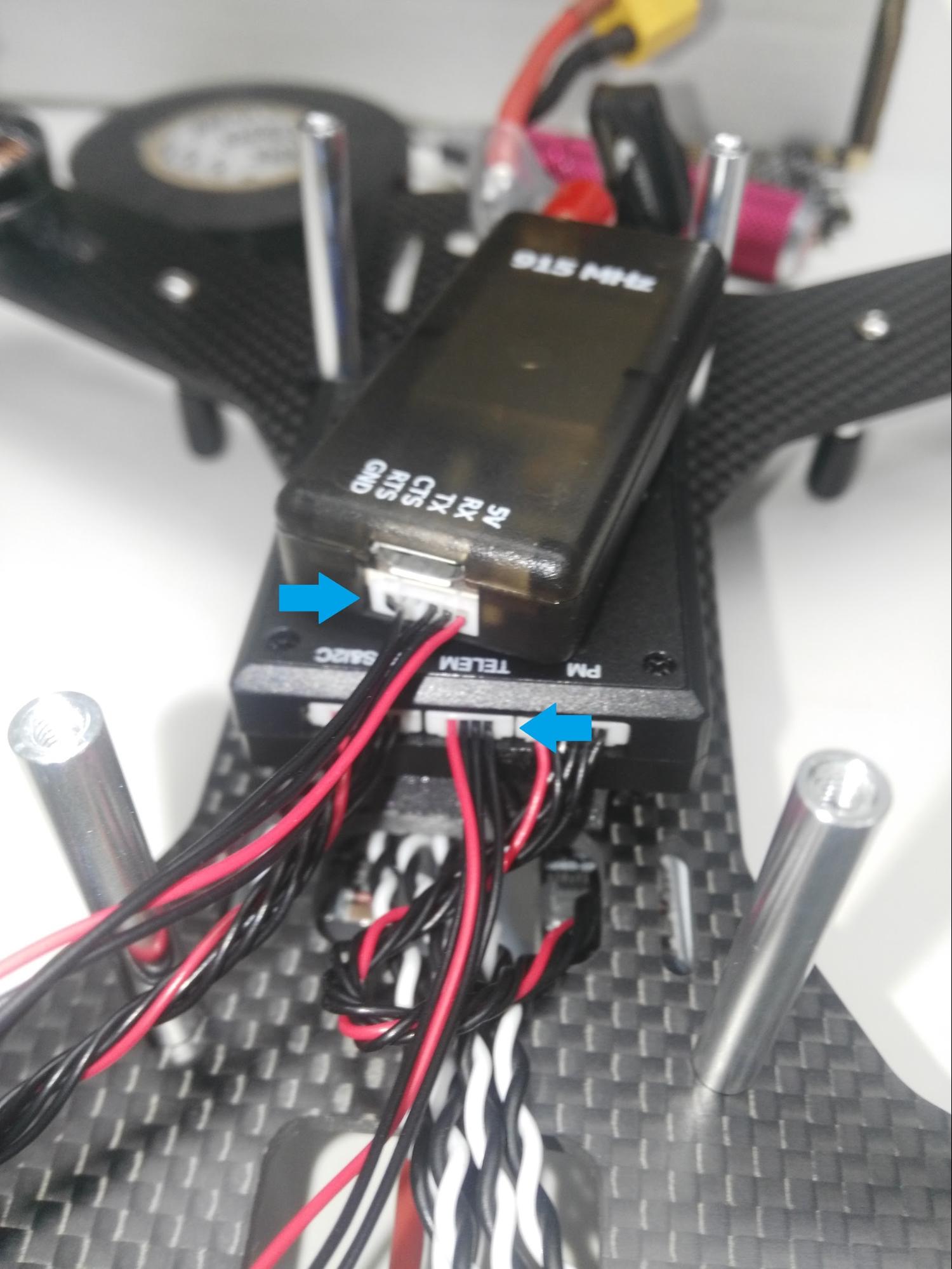
그런 다음 원격 측정 라디오 키트에 포함 된 양면 테이프를 사용하여 라디오를 장착합니다 (이 조립 경우에는 아래의 그림과 같이 PDB 아래에 무선장치를 장착하였습니다).
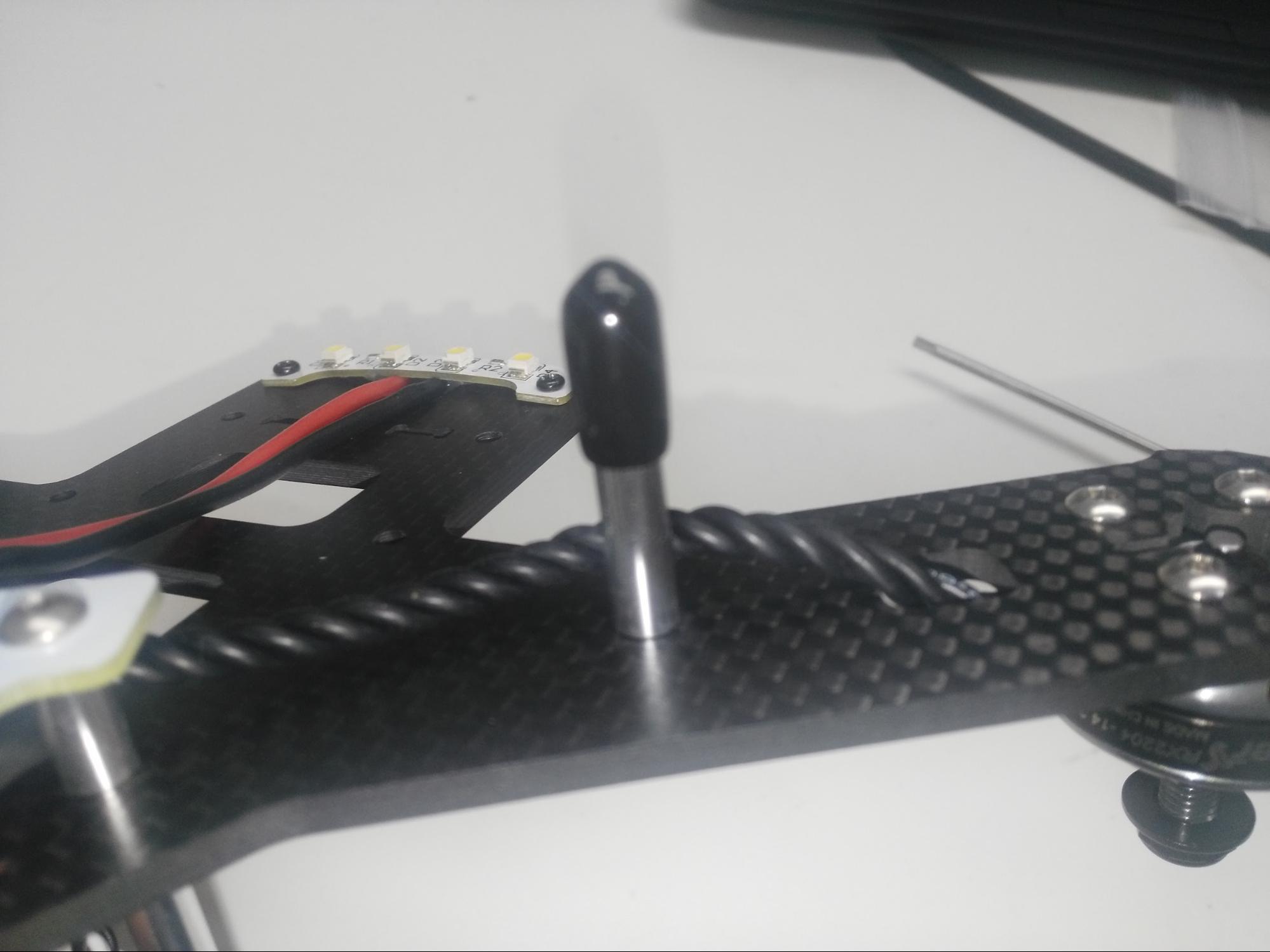
Step 16: Attach landing standoffs to the arms
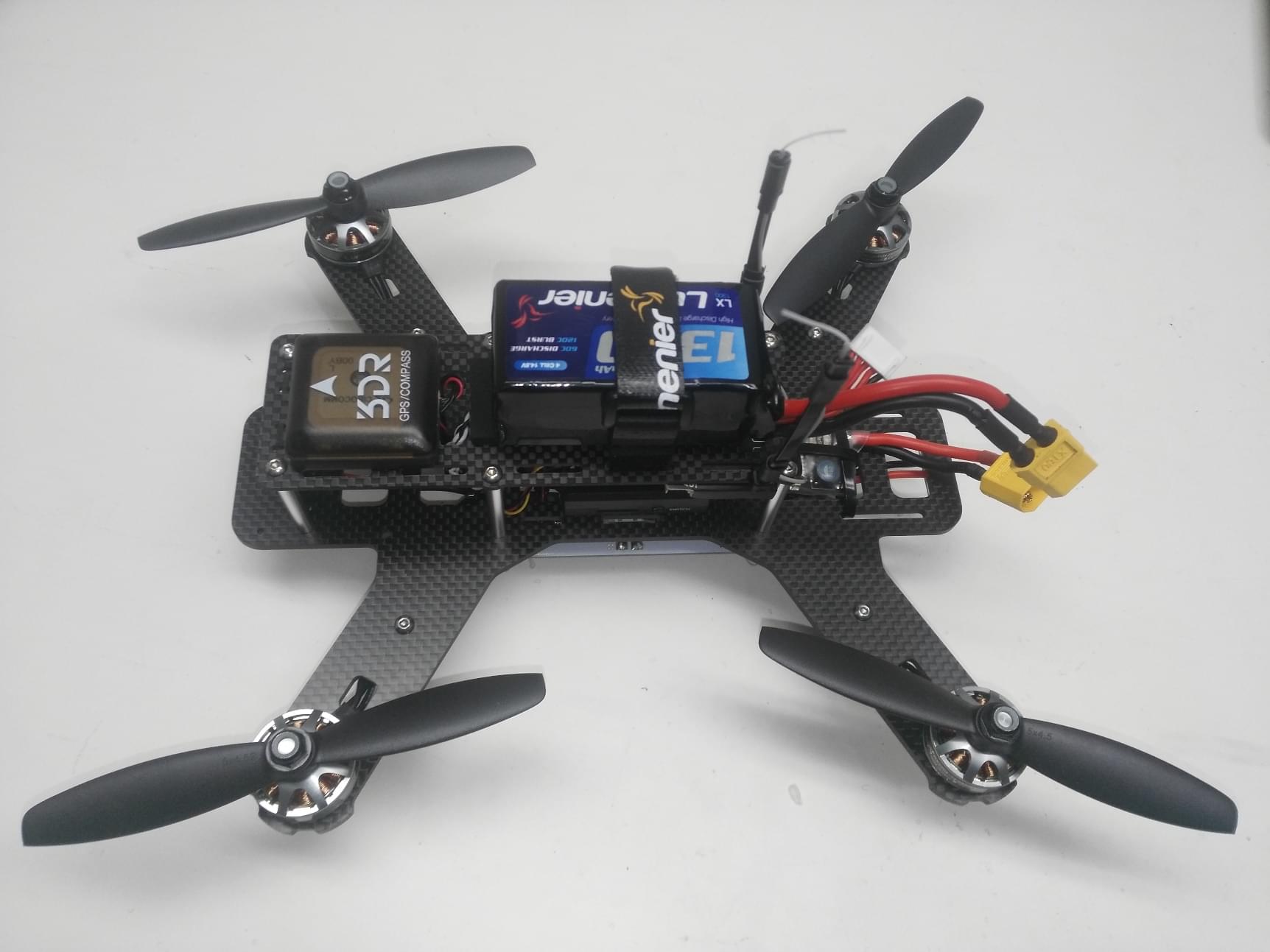
Step 17: Attach the battery foam and velcro battery strap to the cover plate (the battery strap and foam come with the frame kit)
이제 프레임의 조립이 완료되었습니다! In the next step we can install and configure the PX4 autopilot.
# PX4 Configuration
QGroundControl is used to install the PX4 autopilot and configure/tune it for the frame. Download and install (opens new window) QGroundControl for your platform.
TIP
Full instructions for installing and configuring PX4 can be found in Basic Configuration. :::
WARNING
Always make sure to have either battery or propellers physically removed from your vehicle during any initial configuration. Better safe than sorry!
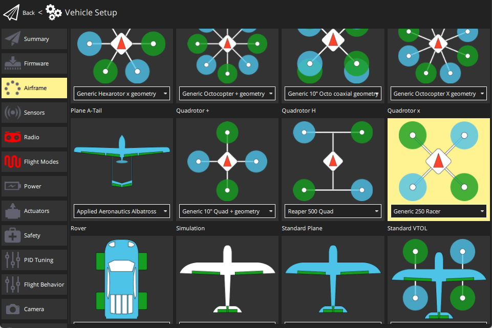
First update the firmware, airframe, and actuator mappings:
-
You will need to select the Generic 250 Racer airframe (Quadrotor x > Generic 250 Racer).
-
- You should not need to update the vehicle geometry (as this is a preconfigured airframe).
- Assign actuator functions to outputs to match your wiring.
- Test the configuration using the sliders.
Then perform the mandatory setup/calibration:
Ideally you should also do:
- ESC Calibration
- Battery
- 4S (4 cell LiPo) with charged cell voltage 4.05V and empty cell voltage 3.4V (or appropriate values for your battery).
- Safety
# 튜닝
Airframe selection sets default autopilot parameters for the frame. These are good enough to fly with, but it is a good idea to tune the parameters for a specific frame build.
For instructions on how, start from Autotune.
# 감사의 글
이 조립 방법은 Abimael Suarez, 3DRobotics에서 제공하였습니다.