# Holybro X500 + Pixhawk4 조립
키트 조립법과 QGroundControl의 PX4 설정법을 설명합니다.
# 주요 정보
- 프레임: Holybro X500
- 비행 컨트롤러: Pixhawk 4
- 조립 시간 (예상): 2시간 (프레임 조립에 75분, 오토파일럿 설치 및 설정에 45분)
- Assembly time (approx.): 3.75 hours (180 minutes for frame, 45 minutes for autopilot installation/configuration)
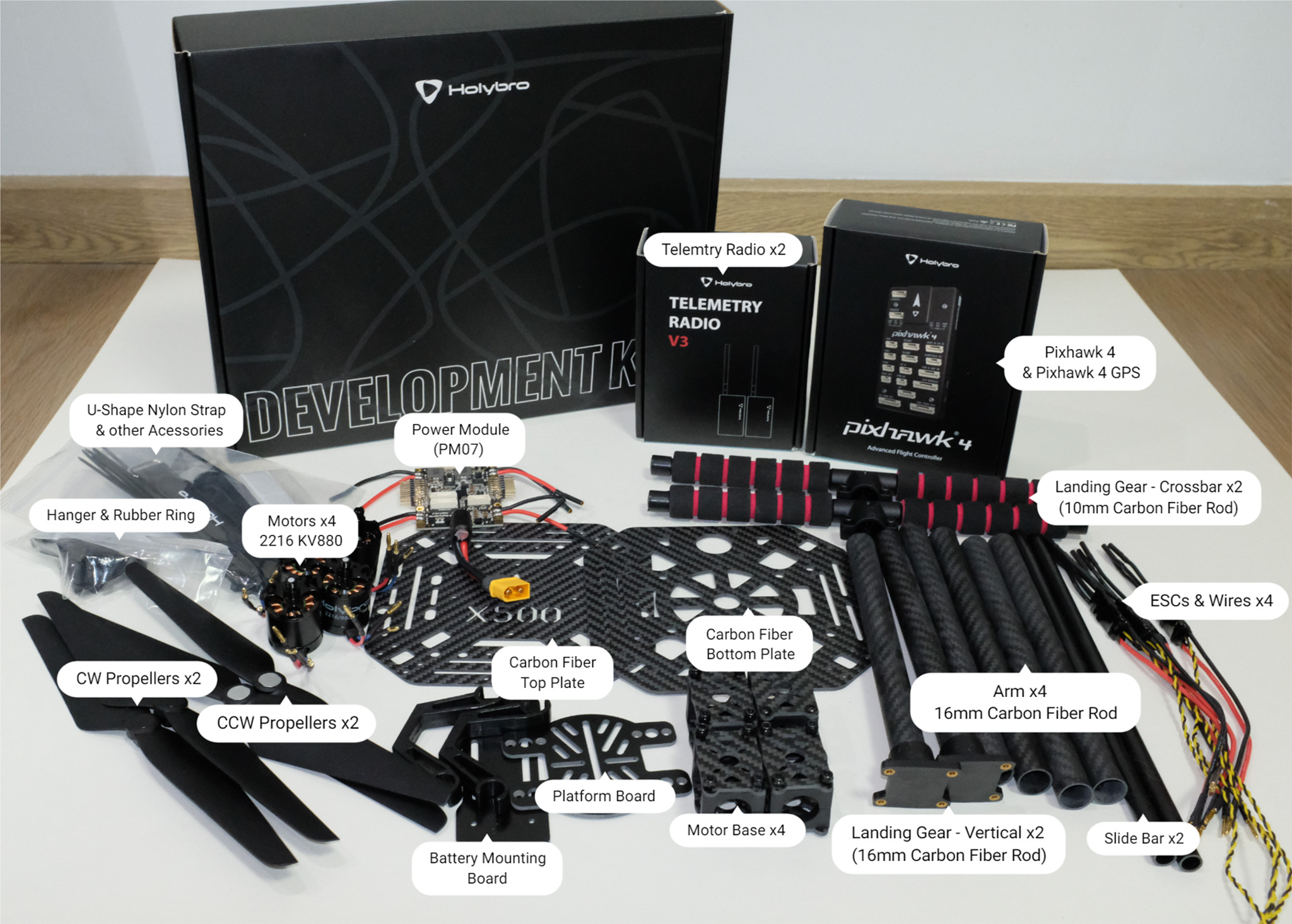
# 부품 명세서
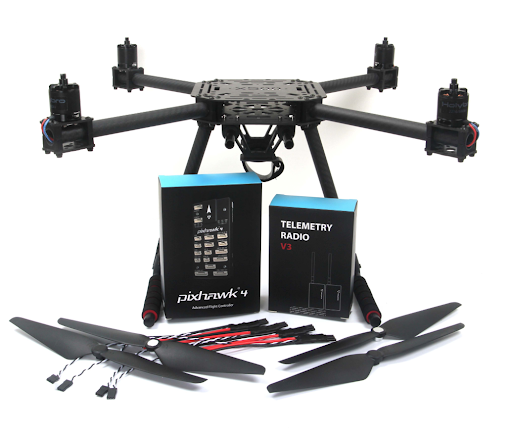
Holybro X500 키드 (opens new window)에는 필수 구성 요소가 포함되어 있습니다.
- Pixhawk 4 autopilot
- Pixhawk 4 GPS (opens new window)
- Power Management - PM07 (opens new window)
- Holybro Motors - 2216 KV880 x4 (opens new window)
- Holybro BLHeli S ESC 20A x4 (opens new window)
- Propellers - 1045 x4 (opens new window)
- 전원 관리 - PM07
- Wheelbase - 500 mm
- 치수 - 410 410 300mm
- 433 MHz Telemetry Radio/915 MHz Telemetry Radio
- 433 MHz Telemetry Radio/915 MHz Telemetry Radio
Additionally you will need a battery and receiver (compatible radio system) if you want to control the drone manually.
# 하드웨어
프레임과 자율비행프로그램 설치를 위한 하드웨어들 입니다.
| 항목 | 설명 | 수량 |
|---|---|---|
| 소켓 캡 나사 | 모터 고정에 사용, 스테인레스 스틸 나사 M3*5 | 16 |
| 탄소 섬유 튜브-암 | 직경 : 16mm, 길이 : 200mm | 4 |
| 모터 베이스 | 6 개의 부품과 4 개의 나사로 구성 4 개의 너트 | 4 |
| 슬라이드 바 | 직경 : 10mm, 길이 : 250mm | 2 |
| 배터리 장착 보드 | 두께: 2mm | 1 |
| 배터리 패드 | 3mm 실리콘 시트 검정 | 1 |
| 철탑 | 구리 너트가 내장된 엔지니어링 플라스틱 | 2 |
| 십자 접시 머리 나사 | 스테인리스 M2.5*5mm | 12 |
| PAN/TILT 플랫폼 보드 | 두께: 2mm | 1 |
| 행거 고무링 개스킷 | 내부 구멍 직경 : 10mm 검정 | 8 |
| 헹거 | 구리 너트가 내장된 엔지니어링 플라스틱 | 8 |
# 전자부품
| 항목 | 패키지 |
|---|---|
| Pixhawk 4 | 1 |
| Pixhawk4 GPS 모듈 | 1 |
| I2C 스플리터 보드 | 2 |
| 6 ~ 6 핀 케이블 (전원) | 3 |
| 4 ~ 4 핀 케이블 (CAN) | 2 |
| 6 ~ 4 핀 케이블 (데이터) | 1 |
# 필요 공구
The following tools are used in this assembly:
- 수신기: FR SKY Taranis
- 배터리: 4S 1300 mAh (opens new window)
- 2.5 mm Hex screwdriver
- 3mm Phillips screwdriver
- 5.5 mm socket wrench or small piler
- Wire cutters
- Precision tweezers
# 패키지
Estimate time to assemble is 3.75 hours (180 minutes for frame, 45 minutes for autopilot installation/configuration)
Start by assembling the landing gear. Unscrew the landing gear screws and insert the vertical pole (figures 1 and 2).
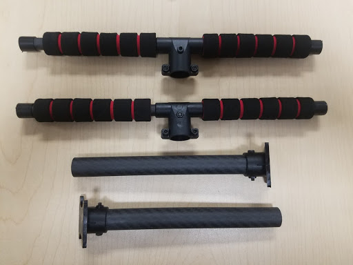
Figure 2: Landing gear components
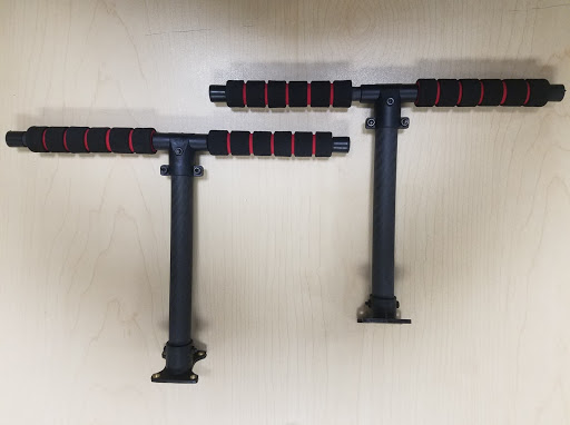
Figure 2: Landing gear assembled
Then put the 4 arms through the 4 motor bases shown in figure 3. Make sure the rods protrude the base slightly and are consistent throughout all 4 arms, and be sure to have the motor wires facing outward.
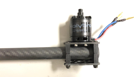
Figure 3: Attach arms to motor bases
Insert 4 nylon screws and nylon standoffs and attach the power module PM07 to the bottom plate using 4 nylon nuts as shown in Figures 4.
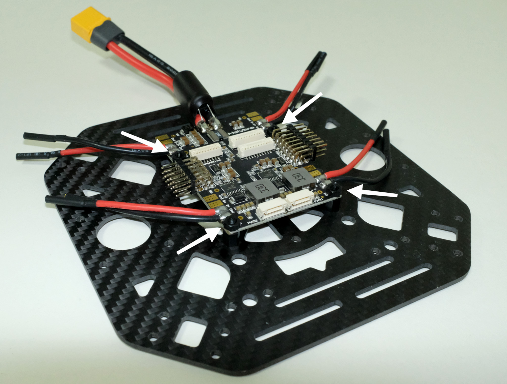
Figure 4: Attach power module
Feed the 4 motor ESCs through each of the arms and connect the 3-wires end to the motors shown in Figure 5.

Figure 5: Connect motors
Connect the ESCs power wires onto the power module PM07, black->black and red->red, ESC PWM signal wires goes to "FMU-PWM-Out". Make sure you connect the motor ESC PWM wires in the correct order. Refer to Figure 7 for airframe motor number and connect to the corrsponding number on the PM07 board.
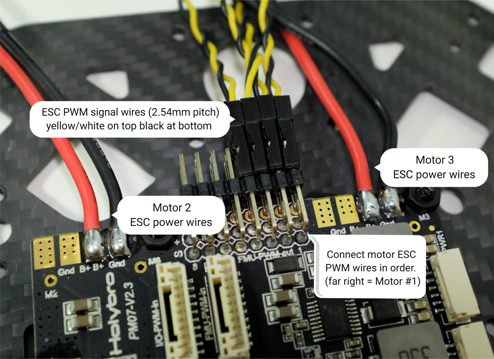 Figure 7: ESC power module and signal wiring
The color on top of the motor indicate the spin direction (figure 7-1), black tip is clockwise, and white tip is counter-clockwise. Make sure the follow the px4 quadrotor x airframe reference for motor direction (figure 7-2).

Figure 7: Motor order/direction diagram
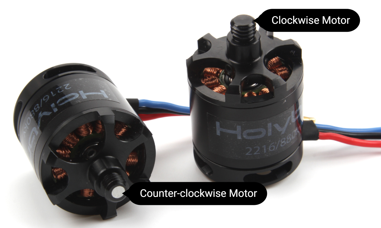
Figure 7-1: Motor direction
Connect the 10 pin cables to FMU-PWM-in, the 6 pin cables to the PWR1 on the PM07 power module.
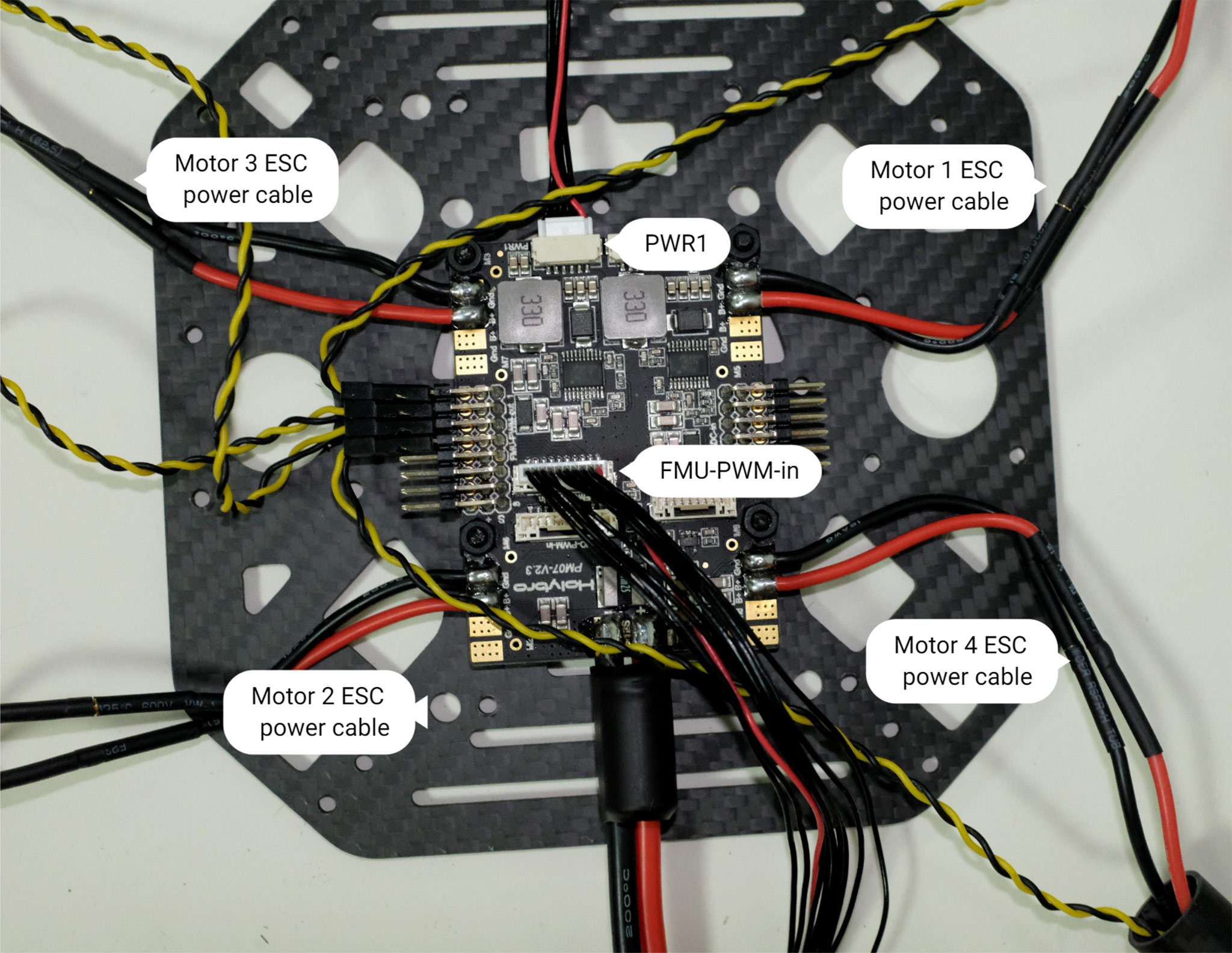
Figure 8: Power module PWM and power wiring
If you want to mount the GPS on the top plate, you can now secure the GPS mount onto the top plate using 4 screws and nuts.

Figure 9: Secure GPS mount onto top plate
Feed the PM07 cables through the top plate. Connect the top and bottom plate by using 4 U-shaped nylon straps, screws, and nuts on each side, ensure that the motor ESC cables are inside the U-shape nylon straps like Figure 10, keep the nut loose.
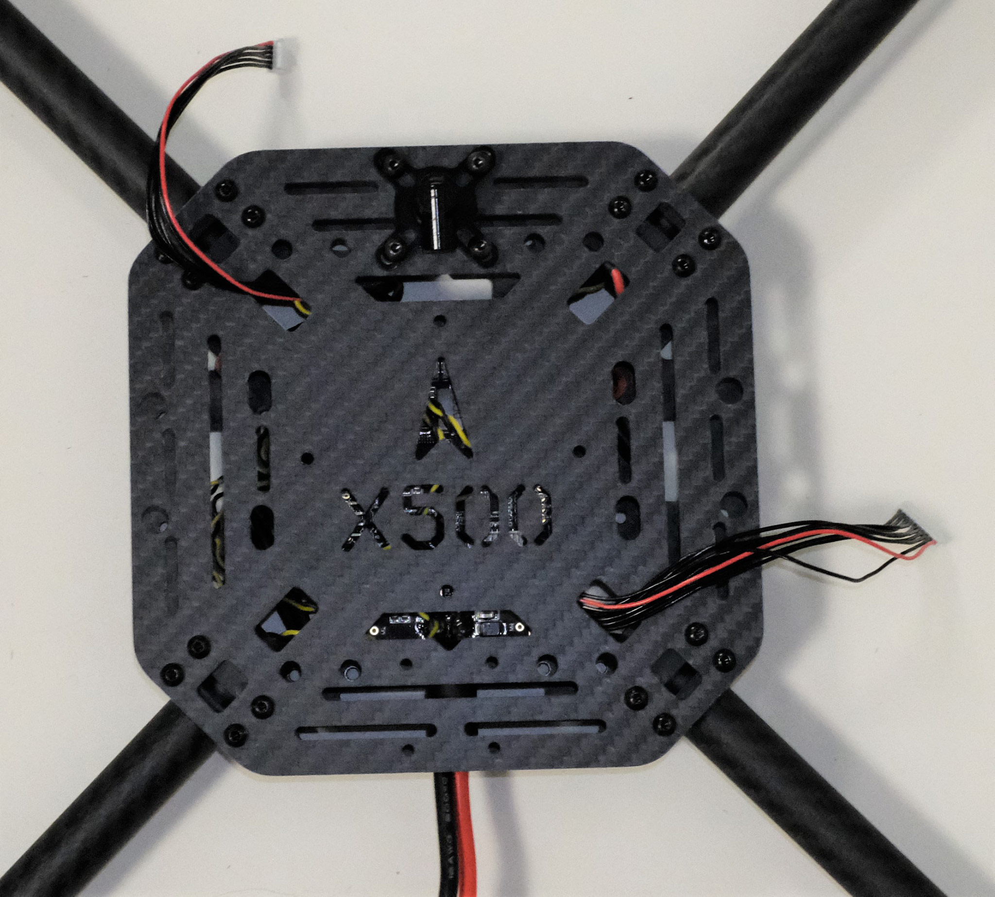
Figure 10-1: Feed power module cables through top plate

Figure 10-2: Connecting top and bottom plate
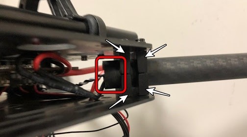
Push the arm tubes a bit into the frame and make sure the amount of protrusion (red square from Figure 11) are consistent on all 4 arms. Ensure all the motors are pointed directly upward, then tighten all the nuts and screws.
Put the hanger gaskets into the 4 hangers and mount them onto the bottom plate using 8 hex screws (Figure 11). The screw holes are noted by the white arrow in Figure 12. We recommend tilting the drone sideway to make the installation easier.

Figure 11: Hanger gaskets
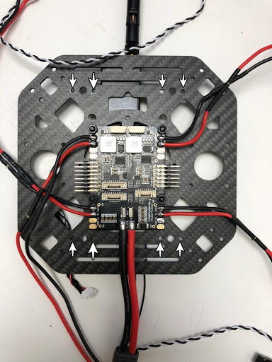
Figure 12: Screw holes
Insert the slide bars onto the hanger rings (Figure 13). Assemble the battery mount and platform board and mount them onto the slide bars as shown in Figure 14.
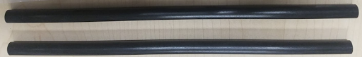
Figure 13: Slide bars

Figure 14: Battery mount on slide bars
Mount the landing gear onto the bottom plate. We recommend tilting the drone sideway to make this installation process easier.
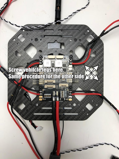
Figure 15: Landing Gear
Use the tape and stick the GPS to the top of the GPS mast and mount the GPS mast. Make sure the arrow on the gps is pointing forward (Figure 16).

Figure 16: GPS and mast
Mount the telemetry radio onto the top plate. Plug the telemetry cable into
TELEM1port and GPS module toGPS MODULEport on the flight controller. Plug the cable from PM07 FMU-PWM-in to FMU-PWM-out and PWR1 toPOWER1on the flight controller, as shown in Figure 17.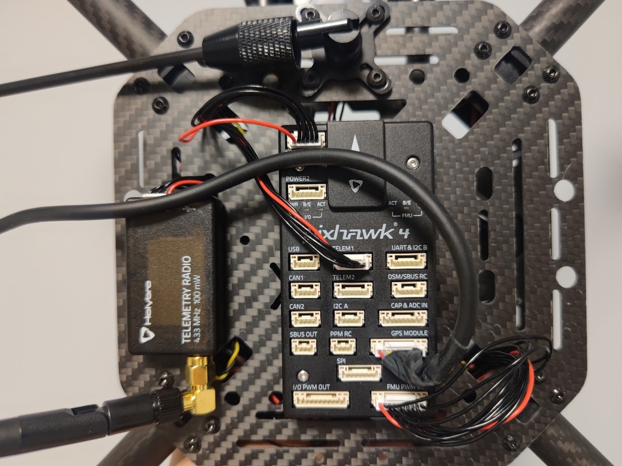
Figure 17: Mount telemetry radio/plug in PWM and Power cables to Flight controller.
Please refer to Pixhawk 4 Quick Start for more information.
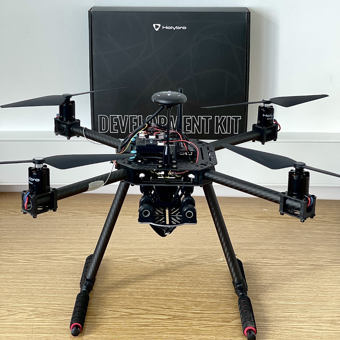
That's it. The fully assembled kit is shown below:
# 조립
TIP
Full instructions for installing and configuring PX4 can be found in Basic Configuration.
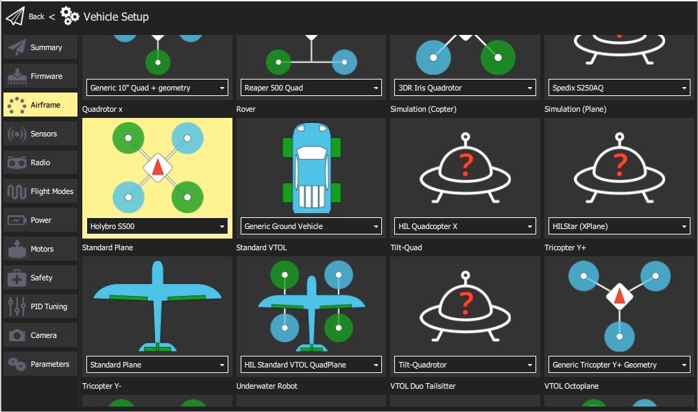
QGroundControl is used to install the PX4 autopilot and configure/tune it for the X500 frame. Download and install (opens new window) QGroundControl for your platform.
First update the firmware and airframe:
Then perform the mandatory setup/calibration:
(그림 2)
# PX4 설치 및 설정
Airframe selection sets default autopilot parameters for the frame. These are good enough to fly with, but it is a good idea to tune the parameters for a specific frame build. For instructions on how, see: Multicopter Basic PID Tuning.
# 튜닝
This build log was provided by the Dronecode Test Flight Team.