# SWD (JTAG) 하드웨어 디버깅 인터페이스
PX4는 일반적으로 ARM 직렬 와이어 디버그(SWD) 인터페이스를 제공하는 자동조종장치 컨트롤러에서 실행됩니다. SWD는 ARM 프로세서에서 JTAG 디버깅을 위한 핀 수가 적은 물리적 인터페이스입니다. SWD 호환 디버그 프로브(예: Segger J-Link EDU Mini, Dronecode Probe 등)와 함께 사용하여 PX4에서 중단점을 설정하고, 실제 장치에서 실행중인 코드를 단계별로 실행할 수 있습니다.
SWD 인터페이스를 사용하여 완전히 비어 있는 보드(USB 부트로더가 설치되지 않은 보드)에 새 부트로더나 펌웨어를 추가할 수 있습니다.
This topic explains how to connect the SWD interface on different boards (debugging itself is then covered in the associated debugging topics).
# SWD 인터페이스 정의
SWD 인터페이스는 다음과 같은 핀으로 구성됩니다.
| 핀 | 신호 형식 | 설명 |
|---|---|---|
Vref | 출력 | 목표 기준 전압: 일부 JTAG 어댑터는 SWD 라인의 전압을 설정하기 위하여 Vref 전압이 필요합니다. 예를 들어, SEGGER J-Link 디버그 프로브에는 Vref가 필요합니다. |
SWDIO | 입출력 | 단일 양방향 데이터 핀. |
SWCLK | 출력 | 클록 신호 |
GND | - | 접지 핀 |
SWD의 "일부"는 아니지만, 자동조종장치에는 직렬 와이어 출력(SWO) 추적 출력 핀이 있을 수 있습니다. 이 핀이 있는 경우에는 이것을 연결하여야 합니다.
| 핀 | 신호 형식 | 설명 |
|---|---|---|
SWO | 출력 | 직렬 와이어 출력 트레이스 출력 핀. 실시간 추적 데이터를 내보내는 SWD와 함께 사용할 수 있습니다. |
# SWD 디버거를 PX4 하드웨어에 연결
Flight controllers commonly provide a single debug port that exposes both the SWD Interface and System Console. This must be connected to an SWD debug probe using an "appropriate" connector.
This connector may come with your flight controller or debug probe. Other options are given below.
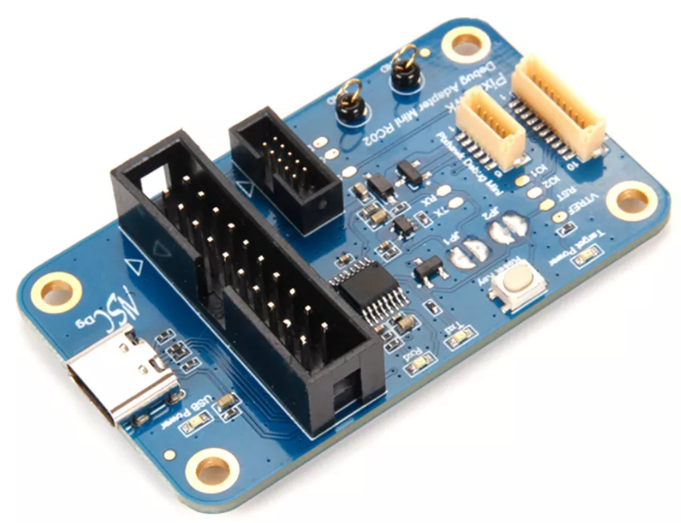
# Holybro Pixhawk Debug Adapter
The Holybro Pixhawk Debug Adapter (opens new window) is highly recommended when debugging controllers that use one of the Pixhawk-standard debug connectors.
It is the easiest way to connect:
- Flight controllers that use either the Pixhawk Debug Full (10-pin SH) or Pixhawk Debug Mini (6-pin SH) debug port, and
- SWD debug probes that support the 10-pin ARM compatible interface standard used by the Segger JLink Mini or 20-pin compatible with the Segger Jlink or STLink.
# Debug Probe Adapters
Some SWD debug probes come with adapters/cables for connecting to common Pixhawk debug ports. Probes that are known to come with connectors are listed below:
- DroneCode Probe: comes with a connector for attaching to the Pixhawk Debug Mini
# Board-specific Adapters
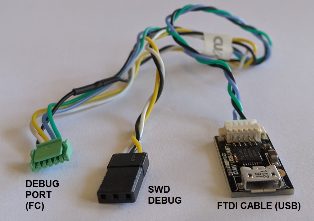
Some manufacturers provide cables to make it easy to connect the SWD interface and System Console.
- CUAV V5nano and CUAV V5+ include this debug cable:
# Custom Cables
You can also create custom cables for connecting to different boards or probes:
- Connect
SWDIO,SWCLKandGNDpins on the debug probe to the corresponding pins on the autopilot. - Connect the
VRefpin, if required by the debug adapter that is being used. - Connect the
SWOpin, if present.
TIP
Where possible, we highly recommend that you create or obtain an adapter board rather than custom cables for connecting to SWD/JTAG debuggers and computers. This reduces the risk or poor wiring contributing to debugging problems, and has the benefit that adapters usually provide a common interface for connecting to multiple popular flight controller boards.
# 자동비행장치 디버그 포트
Flight controllers commonly provide a single debug port that exposes both the SWD Interface and System Console.
The Pixhawk Connector Standards formalize the port that must be used in each FMU version. However there are still many boards that use different pinouts or connectors, so we recommend you check the documentation for your autopilot to confirm port location and pinout.
The debug port location and pinouts for a subset of autopilots are linked below:
| 자동조종장치 | 커넥터 |
|---|---|
| Holybro Pixhawk 5X (FMUv5x) | Pixhawk Debug Full |
| Holybro Durandal | Pixhawk Debug Mini |
| Holybro Kakute F7 | Solder pads |
| Holybro Pixhawk 4 Mini (FMUv5) | Pixhawk Debug Mini |
| Holybro Pixhawk 4 (FMUv5) | Pixhawk Debug Mini |
| Drotek Pixhawk 3 Pro (FMU-v4pro) | Pixhawk Debug Mini |
| CUAV V5+ | 6-pin JST GH Digikey: BM06B-GHS-TBT(LF)(SN)(N) (opens new window) (vertical mount), SM06B-GHS-TBT(LF)(SN)(N) (opens new window) (side mount) |
| CUAV V5nano | 6-pin JST GH Digikey: BM06B-GHS-TBT(LF)(SN)(N) (opens new window) (vertical mount), SM06B-GHS-TBT(LF)(SN)(N) (opens new window) (side mount) |
| 3DR Pixhawk | ARM 10-pin JTAG Connector (also used for FMUv2 boards including: mRo Pixhawk, HobbyKing HKPilot32). |
# Pixhawk Connector Standard Debug Ports
The Pixhawk project has defines a standard pinout and connector type for different Pixhawk FMU releases:
TIP
Check your specific board to confirm the port used.
| FMU 버전 | Pixhawk 버전 | 디버그 인터페이스 |
|---|---|---|
| FMUv2 | Pixhawk / Pixhawk 1 | 10핀 ARM 디버그 |
| FMUv3 | Pixhawk 2 | 6핀 SUR 디버그 |
| FMUv4 | Pixhawk 3 | Pixhawk Debug Mini |
| FMUv5 | Pixhawk 4 FMUv5 | Pixhawk Debug Mini |
| FMUv5X | Pixhawk 5X | Pixhawk Debug Full |
| FMUv6 | Pixhawk 6 | Pixhawk Debug Full |
| FMUv6X | Pixhawk 6X | Pixhawk Debug Full |
Note
There FMU and Pixhawk versions are (only) consistent after FMUv5X.
# Pixhawk Debug Mini (6-Pin SH Debug Port)
The Pixhawk Connector Standard (opens new window) defines the Pixhawk Debug Mini, a 6-Pin SH Debug Port that provides access to both SWD pins and the System Console.
This is used in FMUv4 and FMUv5.
The pinout is as shown below (SWD pins highlighted):
| 디버그 포트 | 핀 |
|---|---|
| 1 | Vtref |
| 2 | 콘솔 TX |
| 3 | 콘솔 RX |
| 4 | SWDIO |
| 5 | SWDCLK |
| 6 | GND |
The debug port definition includes the following solder pads (on board next to connector):
| 디버그 포트 | 핀 | 전압 |
|---|---|---|
| 패드 | 신호 | 볼트 |
| 1 | NRST (reset) | +3.3V |
| 2 | GPIO1 (여분의 GPIO) | +3.3V |
| 3 | GPIO2 (여분의 GPIO) | +3.3V |
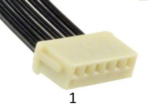
The socket is a 6-pin JST SH - Digikey number: BM06B-SRSS-TBT(LF)(SN) (opens new window) (vertical mount), SM06B-SRSS-TBT(LF)(SN) (opens new window)(side mount).
You can connect to the debug port using a cable like this one (opens new window).
# Pixhawk Debug Full (10-Pin SH Debug Port)
The Pixhawk Connector Standard (opens new window) defines Pixhawk Debug Full, a 10-Pin SH Debug Port that provides access to both SWD pins and the System Console. This essentially moves the solder pads from beside the Pixhawk Debug Mini into the connector, and also adds an SWO pin.
This port is specified for use in FMUv5x, FMUv6, FMUv6x.
The pinout is as shown below (SWD pins highlighted):
| 디버그 포트 | 핀 |
|---|---|
| 1 | Vtref |
| 2 | 콘솔 TX |
| 3 | 콘솔 RX |
| 4 | SWDIO |
| 5 | SWDCLK |
| 6 | SWO |
| 7 | NFC GPIO |
| 8 | PH11 |
| 9 | nRST |
| 10 | GND |
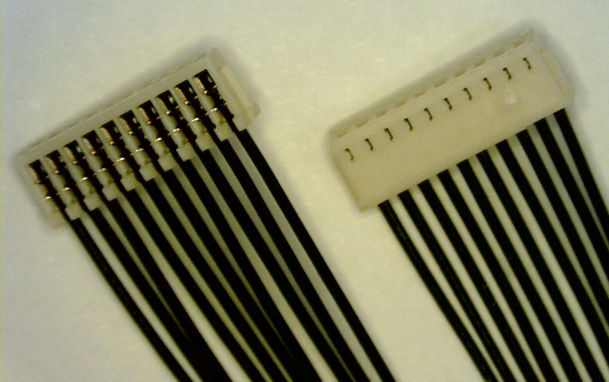
The socket is a 10-pin JST SH - Digikey number: BM10B-SRSS-TB(LF)(SN) (opens new window) (vertical mount) or SM10B-SRSS-TB(LF)(SN) (opens new window) (side mount).
You can connect to the debug port using a cable like this one (opens new window).
# 디버그 프로브
The following section outlines some popular debug probes and adaptors for connecting them to autopilots running PX4.
# Segger JLink EDU Mini Debug Probe
The Segger JLink EDU Mini (opens new window) is an inexpensive and popular SWD debug probe. The probe's connector pinout looks like the image below (connect to this using an ARM 10-pin mini connector like FTSH-105-01-F-DV-K (opens new window)).

The pin mapping to connect the J-Link Edu Mini to Pixhawk Debug Mini is shown below (note, the - indicates a pin that is not required for SWD).
| 디버그 포트 | J-Link Mini |
|---|---|
| 1 (Vtref) | 1 |
| 2 (콘솔 TX) | - |
| 3 (콘솔 RX) | - |
| 4 (SWDIO) | 2 |
| 5 (SWDCLK) | 4 |
| 6 (GND) | 3 또는 5 |
TIP
From the table above you can infer the connections for autopilots that do not use the standard port.
# Dronecode Probe
The Dronecode Probe (opens new window) is a generic JTAG/SWD + UART console adapter compatible with most ARM Cortex based designs, and in particular with Pixhawk series flight controllers (and other hardware that PX4 supports).
The probe's USB interface exposes two separate virtual serial port interfaces: one for connecting to the System Console (UART) and the other for an embedded GDB server (SWD interface).
The probe provides a DCD-M connector cable for attaching to the Pixhawk Debug Mini.
Note
The 6-pos DF13 connector that comes with the probe cannot be used for SWD debugging (it is for using the System Console).
Note
The Dronecode Probe is based on the Black Magic Probe.
# Black Magic Probe
The Black Magic Probe (opens new window) is much like the Dronecode probe but does not come with the same adapters for directly connecting to Pixhawk series flight controllers.
Adapters can be purchased separately:
- Drone Code Debug Adapter (opens new window) (1 BIT SQUARED).
# 다음 단계
You've now connected the flight controller to an SWD debug probe!
The following topics explain how to start on-target debugging:
← 임베디드 디버깅 GDB SWD 디버깅 →