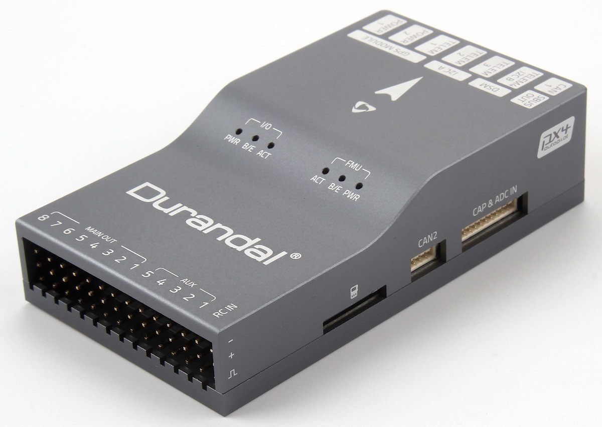
Holybro Durandal
Durandal® is the latest update to the successful family of Holybro flight controllers. It was designed and developed by Holybro.
At high level, some of the key features are:
- Integrated temperature control for sensors.
- Powerful STM32H7 microcontroller running at 480MHz. 2 MB of Flash memory and 1 MB of RAM.
- New sensors with higher temperature stability.
- Internal vibration isolation system.
- Dual high-performance, low-noise IMUs on board are designed for demanding stabilization applications.
A summary of the key features, assembly, and purchase links can be found below.
This flight controller is manufacturer supported.
Quick Summary
Technical Specifications
- Main FMU Processor: STM32H743
- 32 Bit Arm ® Cortex® -M7, 480MHz, 2MB memory, 1MB RAM
- IO Processor: STM32F100
- 32 Bit Arm ® Cortex® -M3, 24MHz, 8KB SRAM
- On-board sensors
- Accel/Gyro: ICM-20689
- Accel/Gyro: BMI088
- Mag: IST8310
- Barometer: MS5611
- GPS: ublox Neo-M8N GPS/GLONASS receiver; integrated magnetometer IST8310
Interfaces
- 8-13 PWM servo outputs (8 from IO, 5 from FMU)
- 6 dedicated PWM/Capture inputs on FMU
- Dedicated R/C input for Spektrum / DSM
- Dedicated R/C input for CPPM and S.Bus
- Dedicated S.Bus servo output and analog / PWM RSSI input
- 5 general purpose serial ports
- 3 with full flow control
- 1 with separate 1.5A current limit
- 3 I2C ports
- 4 SPI buses
- 1 internal high speed SPI sensor bus with 4 chip selects and 6 DRDYs
- 1 internal low noise SPI bus dedicated for XXX
- Barometer with 2 chip selects, no DRDYs
- 1 internal SPI bus dedicated for FRAM
- Supports temperature control located on sensor module
- 1 external SPI buses
- Up to 2 CANBuses for dual CAN
- Each CANBus has individual silent controls or ESC RX-MUX control
- Analog inputs for voltage / current of 2 batteries
- 2 additional analog inputs
Electrical Data
- Power module output: 4.9~5.5V
- Max input voltage: 6V
- Max current sensing: 120A
- USB Power Input: 4.75~5.25V
- Servo Rail Input: 0~36V
Mechanical Data
- Dimensions: 80x45x20.5mm
- Weight: 68.8g
Other Characteristics
- Operating temperature: ~40~85C
- Storage temperature: -40~85C
- CE
- FCC
- RoHS compliant (lead-free)
For more information see: Durandal Technical Data Sheet.
Purchase
Order from Holybro.
Connections
The locations of ports/connections are shown here (and below in the pinouts section).
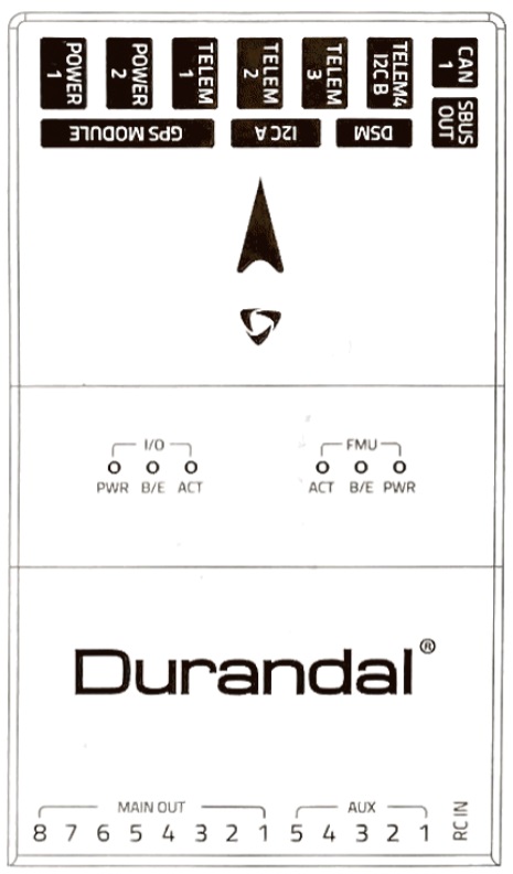
Top
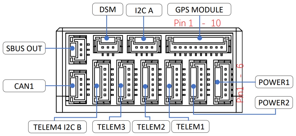
Front
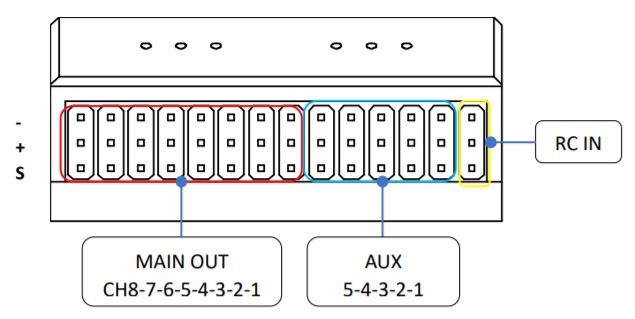
Back
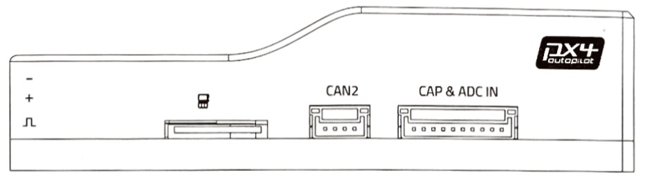
Right
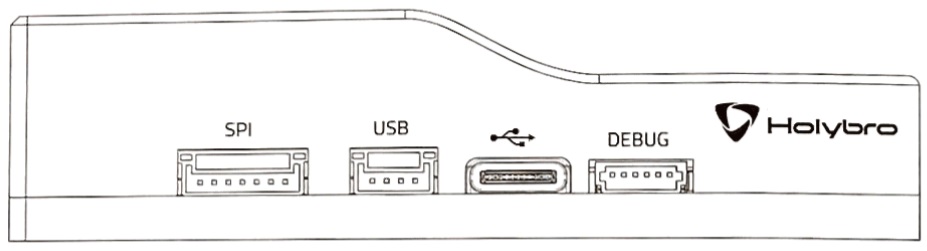
Left
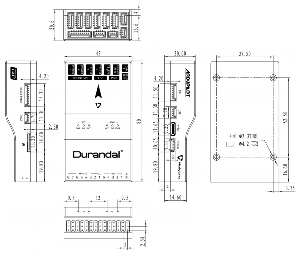
Dimensions
All dimensions are in millimeters.
Assembly/Setup
The Durandal Wiring Quick Start provides instructions on how to assemble required/important peripherals including GPS, Power Management Board etc.
Building Firmware
Most users will not need to build this firmware! It is pre-built and automatically installed by QGroundControl when appropriate hardware is connected.
To build PX4 for this target:
make holybro_durandal-v1_default
Serial Port Mapping
| UART | Device | Port |
|---|---|---|
| USART1 | /dev/ttyS0 | GPS1 |
| USART2 | /dev/ttyS1 | TELEM1 |
| USART3 | /dev/ttyS2 | TELEM2 |
| UART4 | /dev/ttyS3 | TELEM4/GPS2 |
| USART6 | /dev/ttyS4 | TELEM3 |
| UART7 | /dev/ttyS5 | Debug Console |
| UART8 | /dev/ttyS6 | PX4IO |
Debug Port
The PX4 System Console and SWD interface run on the Debug Port.
The port has a standard serial pinout and can be connected to a standard FTDI cable (3.3V, but it's 5V tolerant) or a Dronecode probe. The pinout uses the standard Dronecode debug connector pinout. Please refer to the wiring page for details of how to wire up this port.
No Debug port is exposed for the I/O board.
Peripherals
Supported Platforms / Airframes
Any multicopter / airplane / rover or boat that can be controlled with normal RC servos or Futaba S-Bus servos.
The complete set of supported configurations can be seen in the Airframes Reference.
Pinouts
Durandal pinouts are listed below. These can also be downloaded from here.
Top Pinouts
Front Pinouts
SUBS Out port
| Pin | Signal | Volt |
|---|---|---|
| 1 (red) | - | - |
| 2 (yellow) | SBUS_OUT/RSSI_IN | +3.3V |
| 3 (black) | GND | GND |
DSM RC port
| Pin | Signal | Volt |
|---|---|---|
| 1 (red) | VDD_3V3 | +3.3V |
| 2 (yellow) | DSM_IN | +3.3V |
| 3 (black) | GND | GND |
I2C A port
| Pin | Signal | Volt |
|---|---|---|
| 1 (red) | VCC | +5V |
| 2 (black) | SCL4 | +3.3V |
| 3 (black) | SDA4 | +3.3V |
| 4 (black) | GND | GND |
CAN1 port
| Pin | Signal | Volt |
|---|---|---|
| 1 (red) | VCC | +5V |
| 2 (black) | CAN H | +3.3V |
| 3 (black) | CAN L | +3.3V |
| 4 (black) | GND | GND |
GPS port
| Pin | Signal | Volt |
|---|---|---|
| 1 (red) | VCC | +5V |
| 2 (black) | TX (out) | +3.3V |
| 3 (black) | RX (in) | +3.3V |
| 4 (black) | SCL1 | +3.3V |
| 5 (black) | SDA1 | +3.3V |
| 6 (black) | SAFETY_SWITCH | +3.3V |
| 7 (black) | SAFETY_SWITCH_LED | +3.3V |
| 8 (black) | VDD_3V3 | +3.3V |
| 9 (black) | BUZZER | +5V |
| 10 (black) | GND | GND |
TELEM4 I2CB ports
| Pin | Signal | Volt |
|---|---|---|
| 1 (red) | VCC | +5V |
| 2 (black) | TX (out) | +3.3V |
| 3 (black) | RX (in) | - |
| 4 (black) | SCL2 | - |
| 5 (black) | SDA2 | +3.3V |
| 6 (black) | GND | GND |
TELEM3, TELEM2, TELEM1 port
| Pin | Signal | Volt |
|---|---|---|
| 1 (red) | VCC | +5V |
| 2 (black) | TX (out) | +3.3V |
| 3 (black) | RX (in) | +3.3V |
| 4 (black) | CTS (in) | +3.3V |
| 5 (black) | RTS (out) | +3.3V |
| 6 (black) | GND | GND |
POWER port
| Pin | Signal | Volt |
|---|---|---|
| 1 (red) | VCC | +5V |
| 2 (black) | VCC | +5V |
| 3 (black) | CURRENT | +3.3V |
| 4 (black) | VOLTAGE | +3.3V |
| 5 (black) | GND | GND |
| 6 (black) | GND | GND |
Back Pinouts
MAIN Out
| Pin | Signal | Volt | + | - |
|---|---|---|---|---|
| 1 | IO_CH1 | +3.3V | VDD_SERVO | GND |
| 2 | IO_CH2 | +3.3V | VDD_SERVO | GND |
| 3 | IO_CH3 | +3.3V | VDD_SERVO | GND |
| 4 | IO_CH4 | +3.3V | VDD_SERVO | GND |
| 5 | IO_CH5 | +3.3V | VDD_SERVO | GND |
| 6 | IO_CH6 | +3.3V | VDD_SERVO | GND |
| 7 | IO_CH7 | +3.3V | VDD_SERVO | GND |
| 8 | IO_CH8 | +3.3V | VDD_SERVO | GND |
AUX Out
| Pin | Signal | Volt | + | - |
|---|---|---|---|---|
| 1 | FMU_CH1 | +3.3V | VDD_SERVO | GND |
| 2 | FMU_CH2 | +3.3V | VDD_SERVO | GND |
| 3 | FMU_CH3 | +3.3V | VDD_SERVO | GND |
| 4 | FMU_CH4 | +3.3V | VDD_SERVO | GND |
| 5 | FMU_CH5 | +3.3V | VDD_SERVO | GND |
RC IN
| Pin | Signal | Volt |
|---|---|---|
| S | SBUS_IN/PPM_IN | +3.3V |
- | VCC | +5V
- | GND | GND
Right-side Pinouts
CAN2 port
| Pin | Signal | Volt |
|---|---|---|
| 1 (red) | VCC | +5V |
| 2 (black) | CAN H | +3.3V |
| 3 (black) | CAN L | +3.3V |
| 4 (black) | GND | GND |
CAP & ADC IN port
| Pin | Signal | Volt |
|---|---|---|
| 1 (red) | VCC | +5V |
| 2 (black) | FMU_CAP6 | +3.3V |
| 3 (black) | FMU_CAP5 | +3.3V |
| 4 (black) | FMU_CAP4 | +3.3V |
| 5 (black) | FMU_CAP3 | +3.3V |
| 6 (black) | FMU_CAP2 | +3.3V |
| 7 (black) | FMU_CAP1 | +3.3V |
| 8 (black) | ADC1_SPARE_1 | +3.3V ++ |
| 9 (black) | ADC1_SPARE_2 | +6.6V ++ |
| 10 (black) | GND | GND |
++ Sensors connected to pins 8, 9 must not send a signal exceeding the indicated voltage.
Left-side Pinouts
DEBUG port
| Pin | Signal | Volt |
|---|---|---|
| 1 (red) | VT | +3.3V |
| 2 (black) | TX | +3.3V |
| 3 (black) | RX | +3.3V |
| 4 (black) | SWDIO | +3.3V |
| 5 (black) | SWCLK | +3.3V |
| 6 (black) | GND | GND |
SPI port
| Pin | Signal | Volt |
|---|---|---|
| 1 (red) | VCC | +5V |
| 2 (black) | SCK | +3.3V |
| 3 (black) | MISO | +3.3V |
| 4 (black) | MOSI | +3.3V |
| 5 (black) | CS1 | +3.3V |
| 6 (black) | CS2 | +3.3V |
| 7 (black) | GND | GND |
USB port
| Pin | Signal | Volt |
|---|---|---|
| 1 (red) | VBUS | +5V |
| 2 (black) | DM | +3.3V |
| 3 (black) | DP | +3.3V |
| 4 (black) | GND | GND |