Collision Prevention
Collision Prevention may be used to automatically slow and stop a vehicle before it can crash into an obstacle. It can be enabled for multicopter vehicles when using acceleration-based Position mode (or VTOL vehicles in MC mode).
It can be enabled for multicopter vehicles in Position mode (with MPC_POS_MODE set to Acceleration based), and can use sensor data from an offboard companion computer, offboard rangefinders over MAVLink, a rangefinder attached to the flight controller, or any combination of the above.
Collision prevention may restrict vehicle maximum speed if the sensor range isn't large enough! It also prevents motion in directions where no sensor data is available (i.e. if you have no rear-sensor data, you will not be able to fly backwards).
TIP
If high flight speeds are critical, consider disabling collision prevention when not needed.
TIP
Ensure that you have sensors/sensor data in all directions that you want to fly (when collision prevention is enabled).
Overview
The vehicle restricts the current velocity in order to slow down as it gets closer to obstacles and adapts the acceleration setpoint in order to disallow collision trajectories. In order to move away from (or parallel to) an obstacle, the user must command the vehicle to move toward a setpoint that does not bring the vehicle closer to the obstacle. The algorithm will make minor adjustments to the setpoint direction if it is determined that a “better” setpoint exists within a fixed margin on either side of the requested setpoint.
Users are notified through QGroundControl while Collision Prevention is actively controlling velocity setpoints.
PX4 software setup is covered in the next section. If you are using a distance sensor attached to your flight controller for collision prevention, it will need to be attached and configured as described in PX4 Distance Sensor. If you are using a companion computer to provide obstacle information see companion setup below.
Supported Rangefinders
Lanbao PSK-CM8JL65-CC5 [Discontinued]
At time of writing PX4 allows you to use the Lanbao PSK-CM8JL65-CC5 IR distance sensor for collision prevention “out of the box”, with minimal additional configuration:
- First attach and configure the sensor, and enable collision prevention (as described above, using CP_DIST).
- Set the sensor orientation using SENS_CM8JL65_R_0.
LightWare LiDAR SF45 Rotating Lidar
PX4 v1.14 (and later) supports the LightWare LiDAR SF45 rotating lidar which provides 320 degree sensing.
Other Rangefinders
Other sensors may be enabled, but this requires modification of driver code to set the sensor orientation and field of view.
- Attach and configure the distance sensor on a particular port (see sensor-specific docs) and enable collision prevention using CP_DIST.
- Modify the driver to set the orientation. This should be done by mimicking the
SENS_CM8JL65_R_0parameter (though you might also hard-code the orientation in the sensor module.yaml file to something likesf0x start -d ${SERIAL_DEV} -R 25- where 25 is equivalent toROTATION_DOWNWARD_FACING). - Modify the driver to set the field of view in the distance sensor UORB topic (
distance_sensor_s.h_fov).
PX4 (Software) Setup
Configure collision prevention by setting the following parameters in QGroundControl:
| Parameter | Description |
|---|---|
| CP_DIST | Set the minimum allowed distance (the closest distance that the vehicle can approach the obstacle). Set negative to disable collision prevention. > Warning This value is the distance to the sensors, not the outside of your vehicle or propellers. Be sure to leave a safe margin! |
| CP_DELAY | Set the sensor and velocity setpoint tracking delay. See Delay Tuning below. |
| CP_GUIDE_ANG | Set the angle (to both sides of the commanded direction) within which the vehicle may deviate if it finds fewer obstacles in that direction. See Guidance Tuning below. |
| CP_GO_NO_DATA | Set to 1 to allow the vehicle to move in directions where there is no sensor coverage (default is 0/False). |
| MPC_POS_MODE | Must be set to Acceleration based. |
Algorithm Description
The data from all sensors are fused into an internal representation of 36 sectors around the vehicle, each containing either the sensor data and information about when it was last observed, or an indication that no data for the sector was available. When the vehicle is commanded to move in a particular direction, all sectors in the hemisphere of that direction are checked to see if the movement will bring the vehicle closer to any obstacles. If so, the vehicle velocity is restricted.
This velocity restriction takes into account both the inner velocity loop tuned by MPC_XY_P, as well as the jerk-optimal velocity controller via MPC_JERK_MAX and MPC_ACC_HOR. The velocity is restricted such that the vehicle will stop in time to maintain the distance specified in CP_DIST. The range of the sensors for each sector is also taken into account, limiting the velocity via the same mechanism.
INFO
If there is no sensor data in a particular direction, velocity in that direction is restricted to 0 (preventing the vehicle from crashing into unseen objects). If you wish to move freely into directions without sensor coverage, this can be enabled by setting CP_GO_NO_DATA to 1.
Delay, both in the vehicle tracking velocity setpoints and in receiving sensor data from external sources, is conservatively estimated via the CP_DELAY parameter. This should be tuned to the specific vehicle.
If the sectors adjacent to the commanded sectors are 'better' by a significant margin, the direction of the requested input can be modified by up to the angle specified in CP_GUIDE_ANG. This helps to fine-tune user input to 'guide' the vehicle around obstacles rather than getting stuck against them.
Range Data Loss
If the autopilot does not receive range data from any sensor for longer than 0.5s, it will output a warning No range data received, no movement allowed. This will force the velocity setpoints in xy to zero. After 5 seconds of not receiving any data, the vehicle will switch into HOLD mode. If you want the vehicle to be able to move again, you will need to disable Collision Prevention by either setting the parameter CP_DIST to a negative value, or switching to a mode other than Position mode (e.g. to Altitude mode or Stabilized mode).
If you have multiple sensors connected and you lose connection to one of them, you will still be able to fly inside the field of view (FOV) of the reporting sensors. The data of the faulty sensor will expire and the region covered by this sensor will be treated as uncovered, meaning you will not be able to move there.
WARNING
Be careful when enabling CP_GO_NO_DATA=1, which allows the vehicle to fly outside the area with sensor coverage. If you lose connection to one of multiple sensors, the area covered by the faulty sensor is also treated as uncovered and you will be able to move there without constraint.
CP_DELAY Delay Tuning
There are two main sources of delay which should be accounted for: sensor delay, and vehicle velocity setpoint tracking delay. Both sources of delay are tuned using the CP_DELAY parameter.
The sensor delay for distance sensors connected directly to the flight controller can be assumed to be 0. For external vision-based systems the sensor delay may be as high as 0.2s.
Vehicle velocity setpoint tracking delay can be measured by flying at full speed in Position mode, then commanding a stop. The delay between the actual velocity and the velocity setpoint can then be measured from the logs. The tracking delay is typically between 0.1 and 0.5 seconds, depending on vehicle size and tuning.
TIP
If vehicle speed oscillates as it approaches the obstacle (i.e. it slows down, speeds up, slows down) the delay is set too high.
CP_GUIDE_ANG Guidance Tuning
Depending on the vehicle, type of environment and pilot skill different amounts of guidance may be desired. Setting the CP_GUIDE_ANG parameter to 0 will disable the guidance, resulting in the vehicle only moving exactly in the directions commanded. Increasing this parameter will let the vehicle choose optimal directions to avoid obstacles, making it easier to fly through tight gaps and to keep the minimum distance exactly while going around objects.
If this parameter is too small the vehicle may feel "stuck" when close to obstacles, because only movement away from obstacles at minimum distance are allowed. If the parameter is too large the vehicle may feel like it slides away from obstacles in directions not commanded by the operator. From testing, 30 degrees is a good balance, although different vehicles may have different requirements.
INFO
The guidance feature will never direct the vehicle in a direction without sensor data. If the vehicle feels stuck with only a single distance sensor pointing forwards, this is probably because the guidance cannot safely adapt the direction due to lack of information.
Algorithm Description
The data from all sensors are fused into an internal representation of 72 sectors around the vehicle, each containing either the sensor data and information about when it was last observed, or an indication that no data for the sector was available. When the vehicle is commanded to move in a particular direction, all sectors in the hemisphere of that direction are checked to see if the movement will bring the vehicle closer than allowed to any obstacles. If so, the vehicle velocity is restricted.
The Algorithm then can be split into two parts, the constraining of the acceleration setpoint coming from the operator, and the compensation of the current velocity of the vehicle.
INFO
If there is no sensor data in a particular direction, movement in that direction is restricted to 0 (preventing the vehicle from crashing into unseen objects). If you wish to move freely into directions without sensor coverage, this can be enabled by setting CP_GO_NO_DATA to 1.
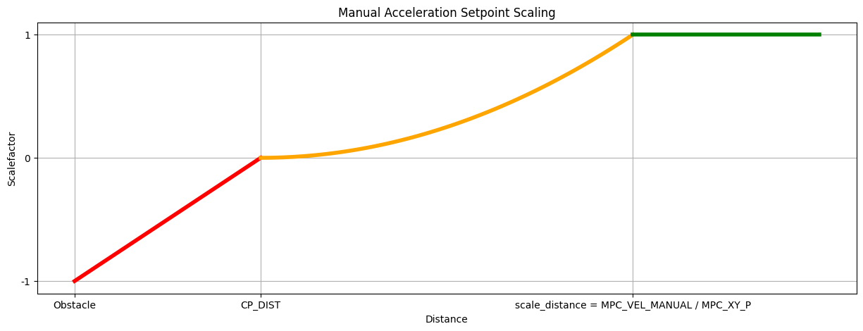
Acceleration Constraining
For this we split out the acceleration setpoint into two components, one parallel to the closest distance to the obstacle and one normal to it. Then we scale each of these components according to the figure below.
Velocity compensation
This velocity restriction takes into account the jerk-optimal velocity controller via MPC_JERK_MAX and MPC_ACC_HOR. Whereby The current velocity is compared with the maximum allowed velocity so that we are still able to break based on the maximal allowed jerk, acceleration and delay. from this we are able to use the proportional gain of the acceleration controller(MPC_XY_VEL_P_ACC) to transform it into an acceleration.
Delay
The delay associated with collision prevention, both in the vehicle tracking velocity setpoints and in receiving sensor data from external sources, is conservatively estimated via the CP_DELAY parameter. This should be tuned to the specific vehicle.
Companion Setup
WARNING
The companion implementation/setup is currently untested (the original companion project was unmaintained and has been archived).
If using a companion computer or external sensor, it needs to supply a stream of OBSTACLE_DISTANCE messages, which should reflect when and where obstacle were detected.
The minimum rate at which messages must be sent depends on vehicle speed - at higher rates the vehicle will have a longer time to respond to detected obstacles. Initial testing of the system used a vehicle moving at 4 m/s with OBSTACLE_DISTANCE messages being emitted at 10Hz (the maximum rate supported by the vision system). The system may work well at significantly higher speeds and lower frequency distance updates.
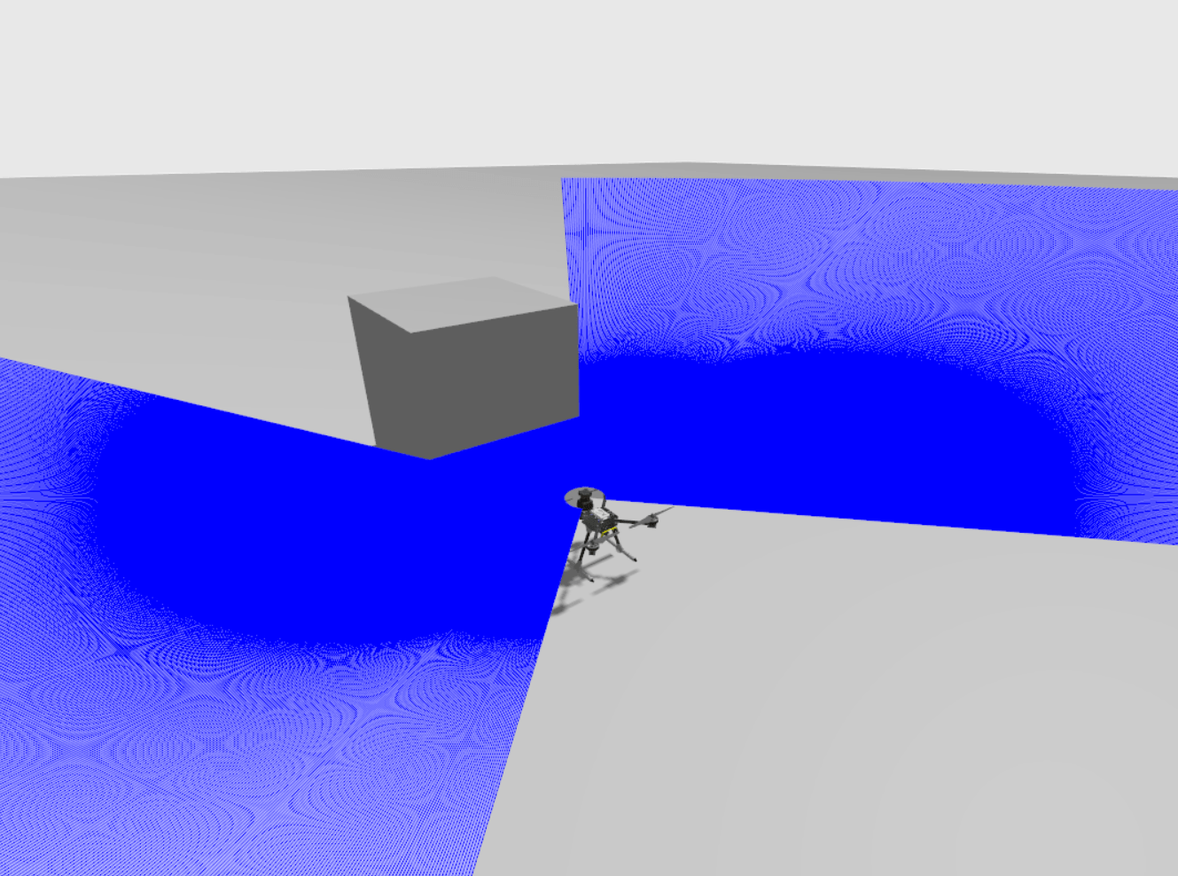
Gazebo Simulation
Collision Prevention can be tested using Gazebo with the x500_lidar_2d model. To do this, start a simulation with the x500 lidar model by running the following command:
sh
make px4_sitl gz_x500_lidar_2dNext, adjust the relevant parameters to the appropriate values and add arbitrary obstacles to your simulation world to test the collision prevention functionality.
The diagram below shows a simulation of collision prevention as viewed in Gazebo.
Development Information/Tools
Plotting Obstacle Distance and Minimum Distance in Real-Time with PlotJuggler
PlotJuggler can be used to monitor and visualize obstacle distances in a real-time plot, including the minimum distance to the closest obstacle.
To use this feature you need to add a reactive Lua script to PlotJuggler, and also configure PX4 to export obstacle_distance_fused UORB topic data. The Lua script works by extracting the obstacle_distance_fused data at each time step, converting the distance values into Cartesian coordinates, and pushing them to PlotJuggler.
The steps are:
Follow the instructions in Plotting uORB Topic Data in Real Time using PlotJuggler
Configure PX4 to publish obstacle distance data (so that it is available to PlotJuggler):
Add the
obstacle_distance_fusedUORB topic to yourdds_topics.yamlso that it is published by PX4:sh- topic: /fmu/out/obstacle_distance_fused type: px4_msgs::msg::ObstacleDistanceFor more information see DDS Topics YAML in uXRCE-DDS (PX4-ROS 2/DDS Bridge)_.
Open PlotJuggler and navigate to the Tools > Reactive Script Editor section. In the Script Editor tab, add following scripts in the appropriate sections:
Global code, executed once:
luaobs_dist_fused_xy = ScatterXY.new("obstacle_distance_fused_xy") obs_dist_min = Timeseries.new("obstacle_distance_minimum")function(tracker_time)
luaobs_dist_fused_xy:clear() i = 0 angle_offset = TimeseriesView.find("/fmu/out/obstacle_distance_fused/angle_offset") increment = TimeseriesView.find("/fmu/out/obstacle_distance_fused/increment") min_dist = 65535 -- Cache increment and angle_offset values at tracker_time to avoid repeated calls local angle_offset_value = angle_offset:atTime(tracker_time) local increment_value = increment:atTime(tracker_time) if increment_value == nil or increment_value <= 0 then print("Invalid increment value: " .. tostring(increment_value)) return end local max_steps = math.floor(360 / increment_value) while i < max_steps do local str = string.format("/fmu/out/obstacle_distance_fused/distances[%d]", i) local distance = TimeseriesView.find(str) if distance == nil then print("No distance data for: " .. str) break end local dist = distance:atTime(tracker_time) if dist ~= nil and dist < 65535 then -- Calculate angle and Cartesian coordinates local angle = angle_offset_value + i * increment_value local y = dist * math.cos(math.rad(angle)) local x = dist * math.sin(math.rad(angle)) obs_dist_fused_xy:push_back(x, y) -- Update minimum distance if dist < min_dist then min_dist = dist end end i = i + 1 end -- Push minimum distance once after the loop if min_dist < 65535 then obs_dist_min:push_back(tracker_time, min_dist) else print("No valid minimum distance found") end
Enter a name for the script on the top right, and press Save. Once saved, the script should appear in the Active Scripts section.
Start streaming the data using the approach described in Plotting uORB Topic Data in Real Time using PlotJuggler. You should see the
obstacle_distance_fused_xyandobstacle_distance_minimumtimeseries on the left.
Note that you have to press Save again to re-enable the scripts after loading a new log file or otherwise clearing data.
Sensor Data Overview
Collision Prevention has an internal obstacle distance map that divides the plane around the drone into 72 Sectors. Internally this information is stored in the obstacle_distance UORB topic. New sensor data is compared to the existing map, and used to update any sections that has changed.
The angles in the obstacle_distance topic are defined as follows:

The data from rangefinders, rotary lidars, or companion computers, is processed differently, as described below.
Rotary Lidars
Rotary Lidars add their data directly to the obstacle_distance uORB topic.
Rangefinders
Rangefinders publish their data to the distance_sensor uORB topic.
This data is then mapped onto the obstacle_distance topic. All sectors which have any overlap with the orientation (orientation and q) of the rangefinder, and the horizontal field of view (h_fov) are assigned that measurement value. For example, a distance sensor measuring from 9.99° to 10.01° the measurements will get added to the bin's corresponding to 5° and 10° covering the arc from 2.5° and 12.5°
INFO
the quaternion q is only used if the orientation is set to ROTATION_CUSTOM.
Companion Computers
Companion computers update the obstacle_distance topic using ROS2 or the OBSTACLE_DISTANCE MAVLink message.