Basic Concepts
This topic provides a basic introduction to drones and using PX4 (it is meant mostly for novice users but is also a good introduction for more experienced users).
If you are already familiar with the basic concepts, you can move on to Basic Assembly to learn how to wire your specific autopilot hardware. To load firmware and set up the vehicle with QGroundControl, see Basic Configuration.
What is a Drone?
A drone, or Unmanned Vehicles (UV), is an unmanned "robotic" vehicle that can be manually or autonomously controlled. They can travel in air, on the ground, on/under the water, and are used for many consumer, industrial, government and military applications, including aerial photography/video, carrying cargo, racing, search and surveying, and so on.
Drones are more formally referred to as Unmanned Aerial Vehicles (UAV), Unmanned Ground Vehicles (UGV), Unmanned Surface Vehicles (USV), Unmanned Underwater Vehicles (UUV).
INFO
The term Unmanned Aerial System (UAS) typically refers to a UAV and all of the other components of a complete system, including a ground control station and/or radio controller, and any other systems used to control the drone, capture, and process data.
Drone Types
There are many different vehicle frames (types), and within the types there are many variations. Some of the types, along with the use cases for which they are most suited are listed below.
- Multicopters — Multi-rotors offer precision hovering and vertical takeoff, at the cost of shorter and generally slower flight. They are the most popular type of flying vehicle, in part because they are easy to assemble, and PX4 has modes that make them easy to fly and very suitable as a camera platform.
- Helicopters — Helicopters similar benefits to Multicopters but are mechanically more complex and more efficient. They are also much harder to fly.
- Planes (Fixed-wing) — Fixed-wing vehicles offer longer and faster flight than multicopters, and hence better coverage for ground surveys etc. However they are harder to fly and land than multicopters, and aren't suitable if you need to hover or fly very slowly (e.g. when surveying vertical structures).
- VTOL (Vertical Takeoff and Landing) - Hybrid Fixed-wing/Multicopter vehicles offer the best of both worlds: take off in vertical mode and hover like a multicopter but transition to forward flight like an airplane to cover more ground. VTOL are often more expensive than either multicopters and fixed-wing aircraft, and harder to build and tune. They come in a number of types: tiltrotors, tailsitters, quadplanes etc.
- Airships/Balloons — Lighter-than-air vehicles that typically offer high altitude long duration flight, often at the cost of having limited (or no) control over speed and direction of flight.
- Rovers — Car-like ground vehicles. They are simple to control and often fun to use. They can't travel as fast as most aircraft, but can carry heavier payloads, and don't use much power when still.
- Boats — Water-surface vehicles.
- Submersibles — Underwater vehicles.
For more information see:
Autopilots
The "brain" of the drone is called an autopilot.
It minimally consists of flight stack software running on a real time OS ("RTOS") on flight controller (FC) hardware. The flight stack provides essential stabilisation and safety features, and usually also some level of pilot assistance for manual flight and automating common tasks, such as taking off, landing, and executing predefined missions.
Some autopilots also include a general-purpose computing system that can provide "higher level" command and control, and that can support more advanced networking, computer vision, and other features. This might be implemented as a separate companion computer, but in future it is increasingly likely to be a fully integrated component.
PX4 Flight Stack
PX4 is powerful open source autopilot flight stack running on the NuttX RTOS.
Some of PX4's key features are:
- Supports many different vehicle frames/types, including: multicopters, fixed-wing aircraft (planes), VTOLs (hybrid multicopter/fixed-wing), ground vehicles, and underwater vehicles.
- Great choice of drone components for flight controller, sensors, payloads, and other peripherals.
- Flexible and powerful flight modes and safety features.
- Robust and deep integration with companion computers and robotics APIs such as ROS 2 and MAVSDK.
PX4 is a core part of a broader drone platform that includes the QGroundControl ground station, Pixhawk hardware, and MAVSDK for integration with companion computers, cameras and other hardware using the MAVLink protocol. PX4 is supported by the Dronecode Project.
Ground Control Stations
Ground Control Stations (GCS) are ground based systems that allow UV operators to monitor and control a drone and its payloads. A subset of the products that are known to work with PX4 are listed below.
QGroundControl
The Dronecode GCS software is called QGroundControl ("QGC"). It runs on Windows, Android, MacOS or Linux hardware, and supports a wide range of screen form factors. You can download it (for free) from here.
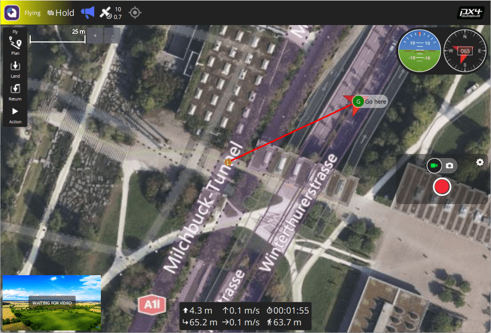
QGroundControl communicates with the drone using a telemetry radio (a bidirectional data link), which allows you to get real-time flight and safety information, and to control the vehicle, camera, and other payloads using a point-and-click interface. On hardware that supports them, you can also manually fly the vehicle using joystick controllers. QGC can also be used to visually plan, execute, and monitor autonomous missions, set geofences, and much more.
QGroundControl desktop versions are also used to install (flash) PX4 firmware and configure PX4 on the drone's autopilot/flight controller hardware.
Auterion Mission Control (AMC)
Auterion Mission Control is a powerful and fully featured ground control station application that is optimized for pilots rather than vehicle configuration. While designed to work with Auterion products, it can be used with "vanilla" PX4.
For more information see:
Drone Components & Parts
Flight Controller
Flight controllers (FC) are the hardware onto which the PX4 flight stack firmware is loaded and run. They are connected to sensors from which PX4 determines its state, and to the actuators/motors that it uses to stabilise and move the vehicle.

PX4 can run on many different types of Flight Controller Hardware, ranging from Pixhawk Series controllers to Linux computers. These include Pixhawk Standard and manufacturer-supported boards. You should select a board that suits the physical constraints of your vehicle, the activities you wish to perform, and cost.
For more information see: Flight Controller Selection
Sensors
PX4 uses sensors to determine vehicle state, which it needs in order to stablise the vehicle and enable autonomous control. The vehicle states include: position/altitude, heading, speed, airspeed, orientation (attitude), rates of rotation in different axes, battery level, and so on.
PX4 minimally requires a gyroscope, accelerometer, magnetometer (compass) and barometer. This minimal set of sensors is incorporated into Pixhawk Series flight controllers (and may also be in other controller platforms).
Additional/external sensors can be attached to the controller. The following sensors are recommended:
A GNSS/GPS or other source of global position is needed to enable all automatic modes, and some manual/assisted modes.
Typically a module that combines a GNSS and Compass is used, as an external compass can be made less susceptible to electromomagnetic interference than the internal compass in the flight controller.
Airspeed sensors are highly recommended for fixed-wing and VTOL-vehicles.
Distance Sensors (Rangefinders) are highly recommended for all vehicle types, as they allow smoother and more robust landings, and enable features such as terrain following on multicopters.
Optical Flow Sensors can be used with distance sensors on multcopters and VTOL to support navigation in GNSS-denied environments.
For more information about sensors see: Sensor Hardware & Setup.
Outputs: Motors, Servos, Actuators
PX4 uses outputs to control: motor speed (e.g. via ESC), flight surfaces like ailerons and flaps, camera triggers, parachutes, grippers, and many other types of payloads.
The outputs may be PWM ports or DroneCAN nodes (e.g. DroneCAN motor controllers). The images below show the PWM output ports for Pixhawk 4 and Pixhawk 4 mini.
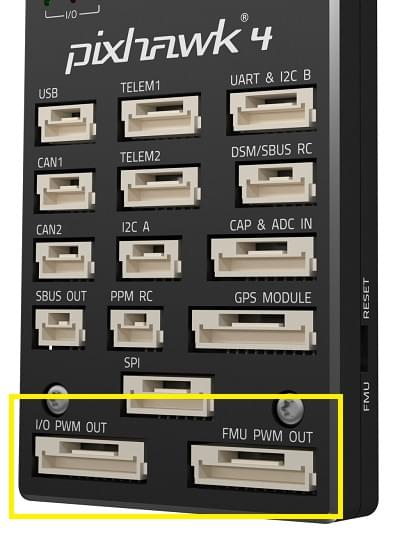
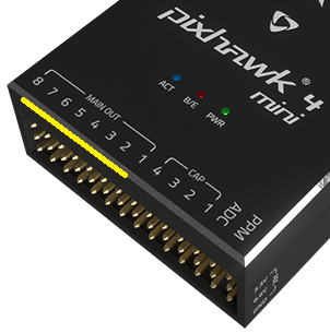
The outputs are divided into MAIN and AUX outputs, and individually numbered (i.e. MAINn and AUXn, where n is 1 to usually 6 or 8). They might also be marked as IO PWM Out and FMU PWM OUT (or similar).
WARNING
A flight controller may only have MAIN PWM outputs (like the Pixhawk 4 Mini), or may have only 6 outputs on either MAIN or AUX. Ensure that you select a controller that has enough ports/outputs for your airframe.
You can connect almost any output to any motor or other actuator, by assigning the associated function ("Motor 1") to the desired output ("AUX1") in QGroundControl: Actuator Configuration and Testing. Note that the functions (motor and control surface actuator positions) for each frame are given in the Airframe Reference.
Notes:
- Pixhawk controllers have an FMU board and may have a separate IO board. If there is an IO board, the
AUXports are connected directly to the FMU and theMAINports are connected to the IO board. Otherwise theMAINports are connected to the FMU, and there are noAUXports. - The FMU output ports can use D-shot or One-shot protocols (as well as PWM), which provide much lower-latency behaviour. This can be useful for racers and other airframes that require better performance.
- There are only 6-8 outputs in
MAINandAUXbecause most flight controllers only have this many PWM/Dshot/Oneshot outputs. In theory there can be many more outputs if the bus supports it (i.e. a UAVCAN bus is not limited to this few nodes).
ESCs & Motors
Many PX4 drones use brushless motors that are driven by the flight controller via an Electronic Speed Controller (ESC) (the ESC converts a signal from the flight controller to an appropriate level of power delivered to the motor).
For information about what ESC/Motors are supported by PX4 see:
- ESC & Motors
- ESC Calibration
- ESC Firmware and Protocols Overview (oscarliang.com)
Battery/Power
PX4 drones are mostly commonly powered from Lithium-Polymer (LiPo) batteries. The battery is typically connected to the system using a Power Module or Power Management Board, which provide separate power for the flight controller and to the ESCs (for the motors).
Information about batteries and battery configuration can be found in Battery Estimation Tuning and the guides in Basic Assembly (e.g. Pixhawk 4 Wiring Quick Start > Power).
Manual Control
Pilots can control a vehicle manually using either a Radio Control (RC) System or a Joystick/Gamepad controller connected via QGroundControl.
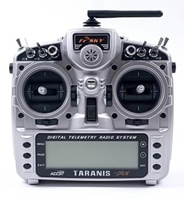
RC systems use a dedicated ground-based radio transmitter and vehicle-based receiver for sending control information. They should always be used when first tuning/testing a new frame design, or when flying racers/acrobatically (and in other cases where low latency is important).
Joystick systems use QGroundControl to encode the control information from a "standard" computer gaming joystick into MAVLink messages, and sent it to the vehicle using the (shared) telemetry radio channel. They can be used for most manual flight use cases such as taking off, surveys, and so on, provided your telemetry channel has a high enough bandwidth/low latency.
Joysticks are often used in integrated GCS/manual control systems because it is cheaper and easier to integrate a joystick than a separate radio system, and for the majority of use cases, the lower latency does not matter. They are also perfect for flying the PX4 simulator, because you can plug them directly into your ground control computer.
INFO
PX4 does not require a manual control system for autonomous flight modes.
Safety Switch
Vehicles may include a safety switch that must be engaged before the vehicle can be armed (when armed, motors are powered and propellers can turn).
This switch is almost always integrated into the GPS module that is connected to the Pixhawk GPS1 port — along with the buzzer and UI LED.
The switch may be disabled by default, though this depends on the particular flight controller and airframe configuration. You can disable/enable use of the switch with the CBRK_IO_SAFETY parameter.
INFO
Safety switches are optional. Many argue that it is safer for users never to approach a powered system, even to enable/disable this interlock.
Buzzer
Vehicles commonly include a buzzer for providing audible notification of vehicle state and readiness to fly (see Tune meanings).
This buzzer is almost always integrated into the GPS module that is connected to the Pixhawk GPS1 port — along with the safety switch and UI LED. You can disable the notification tunes using the parameter CBRK_BUZZER.
LEDs
Vehicles should have a superbright UI RGB LED that indicates the current readiness for flight.
Historically this was included in the flight controller board. On more recent flight controllers this is almost always an I2C peripheral integrated into the GPS module that is connected to the Pixhawk GPS1 port — along with the safety switch and buzzer.
Data/Telemetry Radios
Data/Telemetry Radios can provide a wireless MAVLink connection between a ground control station like QGroundControl and a vehicle running PX4. This makes it possible to tune parameters while a vehicle is in flight, inspect telemetry in real-time, change a mission on the fly, etc.
Offboard/Companion Computer
A Companion Computer (also referred to as "mission computer" or "offboard computer"), is a separate on-vehicle computer that communicates with PX4 to provide higher level command and control.
The companion computer usually runs Linux, as this is a much better platform for "general" software development, and allows drones to leverage pre-existing software for computer vision, networking, and so on.
The flight controller and companion computer may be pre-integrated into a single baseboard, simplifying hardware development, or may be separate, and are connected via a serial cable, Ethernet cable, or wifi. The companion computer typically communicates with PX4 using a high level Robotics API such as MAVSDK or ROS 2.
Relevant topics include:
- Companion Computers
- Off-board Mode - Flight mode for offboard control of PX4 from a GCS or companion computer.
- Robotics APIs
SD Cards (Removable Memory)
PX4 uses SD memory cards for storing flight logs, and they are also required in order to use UAVCAN peripherals and fly missions.
By default, if no SD card is present PX4 will play the format failed (2-beep) tune twice during boot (and none of the above features will be available).
TIP
The maximum supported SD card size on Pixhawk boards is 32GB. The SanDisk Extreme U3 32GB and Samsung EVO Plus 32 are highly recommended.
SD cards are never-the-less optional. Flight controllers that do not include an SD Card slot may:
- Disable notification beeps are disabled using the parameter CBRK_BUZZER.
- Stream logs to another component (companion).
- Store missions in RAM/FLASH.
Payloads
Payloads are equipment carried by the vehicle to meet user or mission objectives, such as cameras in surveying missions, instruments used in for inspections such as radiation detectors, and cargo that needs to be delivered. PX4 supports many cameras and a wide range of payloads.
Payloads are connected to Flight Controller outputs, and can be triggered automatically in missions, or manually from an RC Controller or Joystick, or from a Ground Station (via MAVLink/MAVSDK commands).
For more information see: Payloads & Cameras
Arming and Disarming
A vehicle is said to be armed when all motors and actuators are powered, and disarmed when nothing is powered. There is also a prearmed state when only servo actuators are powered, which is primarily used for testing.
A vehicle is usually disarmed on the ground, and must be armed before taking off in the current flight mode.
WARNING
Armed vehicles are dangerous because propellers can start spinning at any time without further user input, and in many cases will start spinning immediately.
Arming and disarming are triggered by default using RC stick gestures. On Mode 2 transmitters you arm by holding the RC throttle/yaw stick on the bottom right for one second, and to disarm you hold the stick on bottom left for one second. It is alternatively possible to configure PX4 to arm using an RC switch or button (and arming MAVLink commands can also be sent from a ground station).
To reduce accidents, vehicles should be armed as little as possible when the vehicle is on the ground. By default, vehicles are:
- Disarmed or Prearmed (motors unpowered) when not in use, and must be explicitly armed before taking off.
- Automatically disarm/prearm if the vehicle does not take off quickly enough after arming (the disarm time is configurable).
- Automatically disarm/prearm shortly after landing (the time is configurable).
- Arming is prevented if the vehicle is not in a "healthy" state.
- Arming is prevented if the vehicle has a safety switch that has not been engaged.
- Arming is prevented if a VTOL vehicle is in fixed-wing mode (by default).
- Arming may be prevented due to a number of other optional arming pre-condition settings, such as low battery.
When prearmed you can still use actuators, while disarming unpowers everything. Prearmed and disarmed should both be safe, and a particular vehicle may support either or both.
TIP
Sometimes a vehicle will not arm for reasons that are not obvious. QGC v4.2.0 (Daily build at time of writing) and later provide an arming check report in Fly View > Arming and Preflight Checks. From PX4 v1.14 this provides comprehensive information about arming problems along with possible solutions.
A detailed overview of arming and disarming configuration can be found here: Prearm, Arm, Disarm Configuration.
Flight Modes
Modes are special operational states that provide different types/levels of vehicle automation and autopilot assistance to the user (pilot).
Autonomous modes are fully controlled by the autopilot, and require no pilot/remote control input. These are used, for example, to automate common tasks like takeoff, returning to the home position, and landing. Other autonomous modes execute pre-programmed missions, follow a GPS beacon, or accept commands from an offboard computer or ground station.
Manual modes are controlled by the user (via the RC control sticks/joystick) with assistance from the autopilot. Different manual modes enable different flight characteristics - for example, some modes enable acrobatic tricks, while others are impossible to flip and will hold position/course against wind.
TIP
Not all modes are available on all vehicle types, and some modes can only be used when specific conditions have been met (e.g. many modes require a global position estimate).
An overview of the flight modes implemented within PX4 for each vehicle can be found below:
Instructions for how to set up your remote control switches to enable different flight modes is provided in Flight Mode Configuration.
PX4 also supports external modes implemented in ROS 2 using the PX4 ROS 2 Control Interface. These are indistinguishable from PX4 internal modes, and can be used to override internal modes with a more advanced version, or to create entirely new functionality. Note that these depend on ROS 2 and can therefore only run on systems that have a companion computer.
Safety Settings (Failsafe)
PX4 has configurable failsafe systems to protect and recover your vehicle if something goes wrong! These allow you to specify areas and conditions under which you can safely fly, and the action that will be performed if a failsafe is triggered (for example, landing, holding position, or returning to a specified point).
INFO
You can only specify the action for the first failsafe event. Once a failsafe occurs the system will enter special handling code, such that subsequent failsafe triggers are managed by separate system level and vehicle specific code.
The main failsafe areas are listed below:
- Low Battery
- Remote Control (RC) Loss
- Position Loss (global position estimate quality is too low).
- Offboard Loss (e.g. lose connection to companion computer)
- Data Link Loss (e.g. lose telemetry connection to GCS).
- Geofence Breach (restrict vehicle to flight within a virtual cylinder).
- Mission Failsafe (prevent a previous mission being run at a new takeoff location).
- Traffic avoidance (triggered by transponder data from e.g. ADSB transponders).
For more information see: Safety (Basic Configuration).
Heading and Directions
All the vehicles, boats and aircraft have a heading direction or an orientation based on their forward motion.
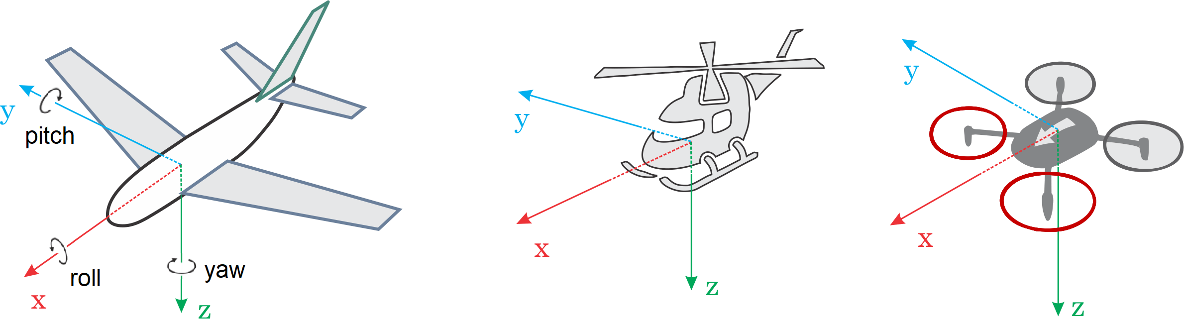
INFO
For a VTOL Tailsitter the heading is relative to the multirotor configuration (i.e. vehicle pose during takeoff, hovering, landing).
It is important to know the vehicle heading direction in order to align the autopilot with the vehicle vector of movement. Multicopters have a heading even when they are symmetrical from all sides! Usually manufacturers use a coloured props or coloured arms to indicate the heading.
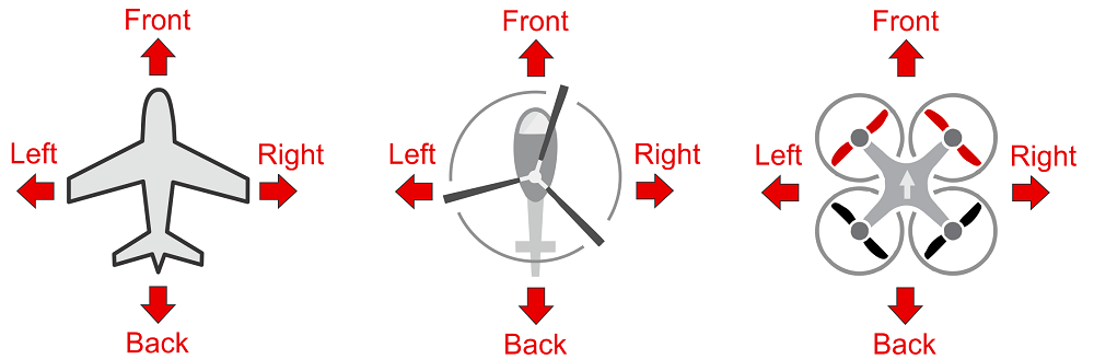
In our illustrations we will use red colouring for the front propellers of multicopter to show heading.
You can read in depth about heading in Flight Controller Orientation