Holybro Pixhawk 4
WARNING
PX4 does not manufacture this (or any) autopilot. Contact the manufacturer for hardware support or compliance issues.
Pixhawk 4® is an advanced autopilot designed and made in collaboration with Holybro® and the PX4 team. It is optimized to run PX4 v1.7 and later, and is suitable for academic and commercial developers.
It is based on the Pixhawk-project FMUv5 open hardware design and runs PX4 on the NuttX OS.

![]()
TIP
This autopilot is supported by the PX4 maintenance and test teams.
Quick Summary
- Main FMU Processor: STM32F765
- 32 Bit Arm® Cortex®-M7, 216MHz, 2MB memory, 512KB RAM
- IO Processor: STM32F100
- 32 Bit Arm® Cortex®-M3, 24MHz, 8KB SRAM
- On-board sensors:
- Accel/Gyro: ICM-20689
- Accel/Gyro: BMI055 or ICM20602
- Magnetometer: IST8310
- Barometer: MS5611
- GPS: u-blox Neo-M8N GPS/GLONASS receiver; integrated magnetometer IST8310
- Interfaces:
- 8-16 PWM outputs (8 from IO, 8 from FMU)
- 3 dedicated PWM/Capture inputs on FMU
- Dedicated R/C input for CPPM
- Dedicated R/C input for Spektrum / DSM and S.Bus with analog / PWM RSSI input
- Dedicated S.Bus servo output
- 5 general purpose serial ports
- 3 I2C ports
- 4 SPI buses
- Up to 2 CANBuses for dual CAN with serial ESC
- Analog inputs for voltage / current of 2 batteries
- Power System:
- Power module output: 4.9~5.5V
- USB Power Input: 4.75~5.25V
- Servo Rail Input: 0~36V
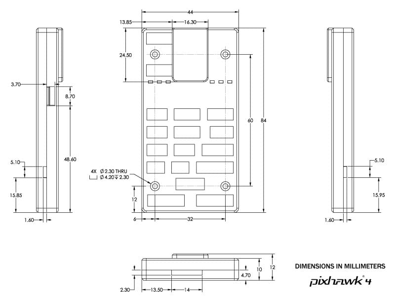
- Weight and Dimensions:
- Weight: 15.8g
- Dimensions: 44x84x12mm
- Other Characteristics:
- Operating temperature: -40 ~ 85°c
Additional information can be found in the Pixhawk 4 Technical Data Sheet.
Where to Buy
Order from Holybro.
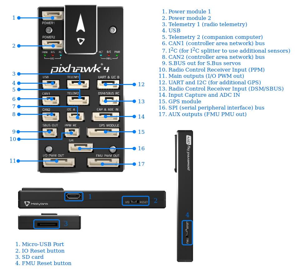
Connectors
WARNING
The DSM/SBUS RC and PPM RC ports are for RC receivers only. These are powered! NEVER connect any servos, power supplies or batteries (or to any connected receiver).
Pinouts
Download Pixhawk 4 pinouts from here.
INFO
Connector pin assignments are left to right (i.e. Pin 1 is the left-most pin). The exception is the debug port(s) (pin 1 is the right-most, as shown below).
Serial Port Mapping
| UART | Device | Port |
|---|---|---|
| UART1 | /dev/ttyS0 | GPS |
| USART2 | /dev/ttyS1 | TELEM1 (flow control) |
| USART3 | /dev/ttyS2 | TELEM2 (flow control) |
| UART4 | /dev/ttyS3 | TELEM4 |
| USART6 | /dev/ttyS4 | RC SBUS |
| UART7 | /dev/ttyS5 | Debug Console |
| UART8 | /dev/ttyS6 | PX4IO |
Dimensions
Voltage Ratings
Pixhawk 4 can be triple-redundant on the power supply if three power sources are supplied. The three power rails are: POWER1, POWER2 and USB.
INFO
The output power rails FMU PWM OUT and I/O PWM OUT (0V to 36V) do not power the flight controller board (and are not powered by it). You must supply power to one of POWER1, POWER2 or USB or the board will be unpowered.
Normal Operation Maximum Ratings
Under these conditions all power sources will be used in this order to power the system:
- POWER1 and POWER2 inputs (4.9V to 5.5V)
- USB input (4.75V to 5.25V)
Absolute Maximum Ratings
Under these conditions the system will not draw any power (will not be operational), but will remain intact.
- POWER1 and POWER2 inputs (operational range 4.1V to 5.7V, 0V to 10V undamaged)
- USB input (operational range 4.1V to 5.7V, 0V to 6V undamaged)
- Servo input: VDD_SERVO pin of FMU PWM OUT and I/O PWM OUT (0V to 42V undamaged)
Assembly/Setup
The Pixhawk 4 Wiring Quick Start provides instructions on how to assemble required/important peripherals including GPS, Power Management Board etc.
Building Firmware
TIP
Most users will not need to build this firmware! It is pre-built and automatically installed by QGroundControl when appropriate hardware is connected.
To build PX4 for this target:
make px4_fmu-v5_defaultDebug Port
The PX4 System Console and SWD interface run on the FMU Debug port, while the I/O console and SWD interface can be accessed via I/O Debug port. In order to access these ports, the user must remove the Pixhawk 4 casing.
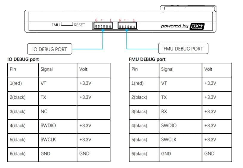
The pinout uses the standard Pixhawk debug connector pinout. For wiring information see:
Peripherals
Supported Platforms / Airframes
Any multicopter / airplane / rover or boat that can be controlled with normal RC servos or Futaba S-Bus servos. The complete set of supported configurations can be seen in the Airframes Reference.