Connecting an RC Receiver to a PX4 Linux-based Autopilot
This topic shows how to setup a PX4 Linux-based autopilot to connect and use a supported RC receiver on any serial port.
For RC types other than S.Bus, you can just connect the receiver directly to the serial ports, or to USB via a USB to TTY serial cable (e.g. like PL2302 USB to Serial TTL converter).
INFO
For an S.Bus receiver (or encoder - e.g. from Futaba, RadioLink, etc.) you will usually need to connect the receiver and device via a signal inverter circuit, but otherwise the setup is the same.
Then Start the PX4 RC Driver on the device, as shown below.
Starting the Driver
To start the RC driver on a particular UART (e.g. in this case /dev/ttyS2):
sh
rc_input start -d /dev/ttyS2For other driver usage information see: rc_input.
Signal Inverter Circuit (S.Bus only)
S.Bus is an inverted UART communication signal.
While some serial ports/flight controllers can read an inverted UART signal, most require a signal inverter circuit between the receiver and serial port to un-invert the signal.
TIP
This circuit is also required to read S.Bus remote control signals through the serial port or USB-to-TTY serial converter.
This section shows how to create an appropriate circuit.
Required Components
- 1x NPN transistor (e.g. NPN S9014 TO92)
- 1x 10K resistor
- 1x 1K resistor
INFO
Any type/model of transistor can be used because the current drain is very low.
Circuit Diagram/Connections
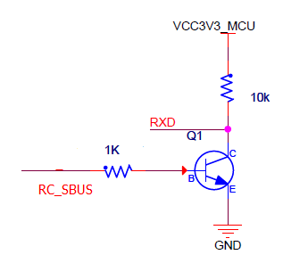
Connect the components as described below (and shown in the circuit diagram):
- S.Bus signal → 1K resistor → NPN transistor base
- NPN transistor emit → GND
- 3.3VCC → 10K resistor → NPN transistor collection → USB-to-TTY rxd
- 5.0VCC → S.Bus VCC
- GND → S.Bus GND

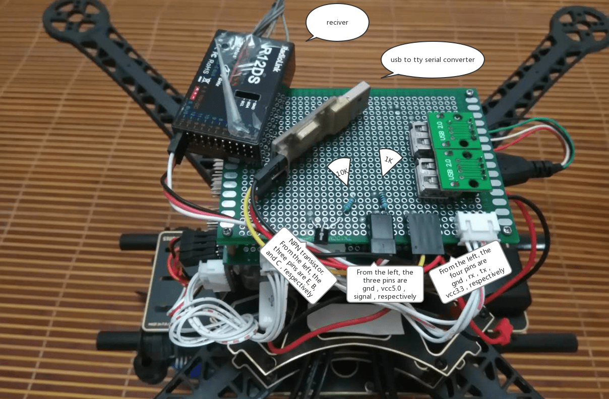
The image below shows the connections on a breadboard.
