将RC接收器连接到基于PX4 Linux的自动驾驶仪
本主题介绍如何设置PX4基于Linux的自动驾驶仪在任何串行端口上连接和使用支持的RC接收器。
对于S.Bus以外的类型,您可以将接收器直接连接到串口,或者使用USB转TTY串行线(例如 PL2302 USB转串行TTL转换器)。
For an S.Bus receiver (or encoder - e.g. from Futaba, RadioLink, etc.) you will usually need to connect the receiver and device via a signal inverter circuit, but otherwise the setup is the same.
然后启动PX4 RC Driver在设备上,如下图。
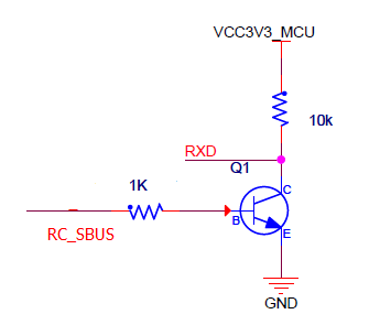
Signal inverter circuit
要在 UART 上启动 RC驱动程序(例如: /dev/ttyS2):
sh
linux_sbus start|stop|status -d <device> -c <channel>S.Bus 是 inverted UART 通信信号。
源代码
S.Bus 是 inverted UART 通信信号。
The command syntax is:
TIP
This circuit is also required to read S.Bus remote control signals through the serial port or USB-to-TTY serial converter.
This section shows how to create an appropriate circuit.
Required components
- 1x NPN 晶体管(例如 NPN S9014 TO92)
- 1x 10K 电阻
- 1x 1K 电阻
INFO
Any type/model of transistor can be used because the current drain is very low.
Circuit diagram/Connections
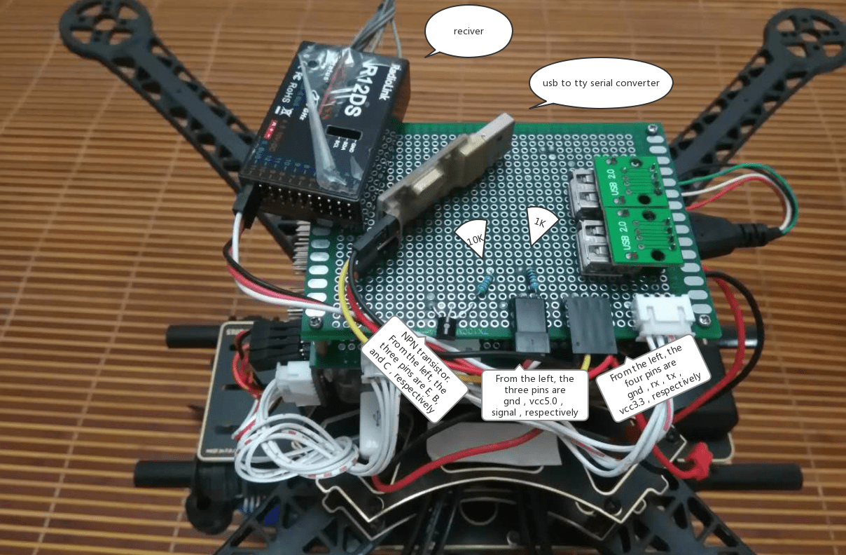
Connect the components as described below (and shown in the circuit diagram):
- S.Bus 信号→1K 电阻→NPN 晶体管
- NPN晶体管发射→GND
- 3.3VCC&→ 10K电阻→ NPN晶体管集合→ USB-to-TTY rxd
- 5.0VCC→S.Bus VCC
- GND → S.Bus GND

The image below shows the connections on a breadboard.
