Compass Power Compensation
Compasses (magnetometers) should be mounted as far as possible from cables that carry large currents, as these induce magnetic fields that may corrupt the compass readings.
This topic explains how to compensate for the induced magnetic fields in the cases where moving the compass is not realistic.
TIP
Moving the compass away from power-carrying cables is the easiest and most effective way to fix this issue, because the strength of the magnetic fields decreases quadratically with the distance from the cable.
INFO
The process is demonstrated for a multicopter, but is equally valid for other vehicle types.
When is Power Compensation Applicable?
Performing this power compensation is advisable only if all the following statements are true:
The compass cannot be moved away from the power-carrying cables.
There is a strong correlation between the compass readings and the thrust setpoint, and/or the battery current.
The drone cables are all fixed in place/do not move (calculated compensation parameters will be invalid if the current-carrying cables can move).
How to Compensate the Compass
Make sure your drone runs a Firmware version supporting power compensation (current master, or releases from v.1.11.0).
Perform the standard compass calibration.
Set the parameter SDLOG_MODE to 2 to enable logging of data from boot.
Set the parameter SDLOG_PROFILE checkbox for Sensor comparison (bit 6) to get more data points.
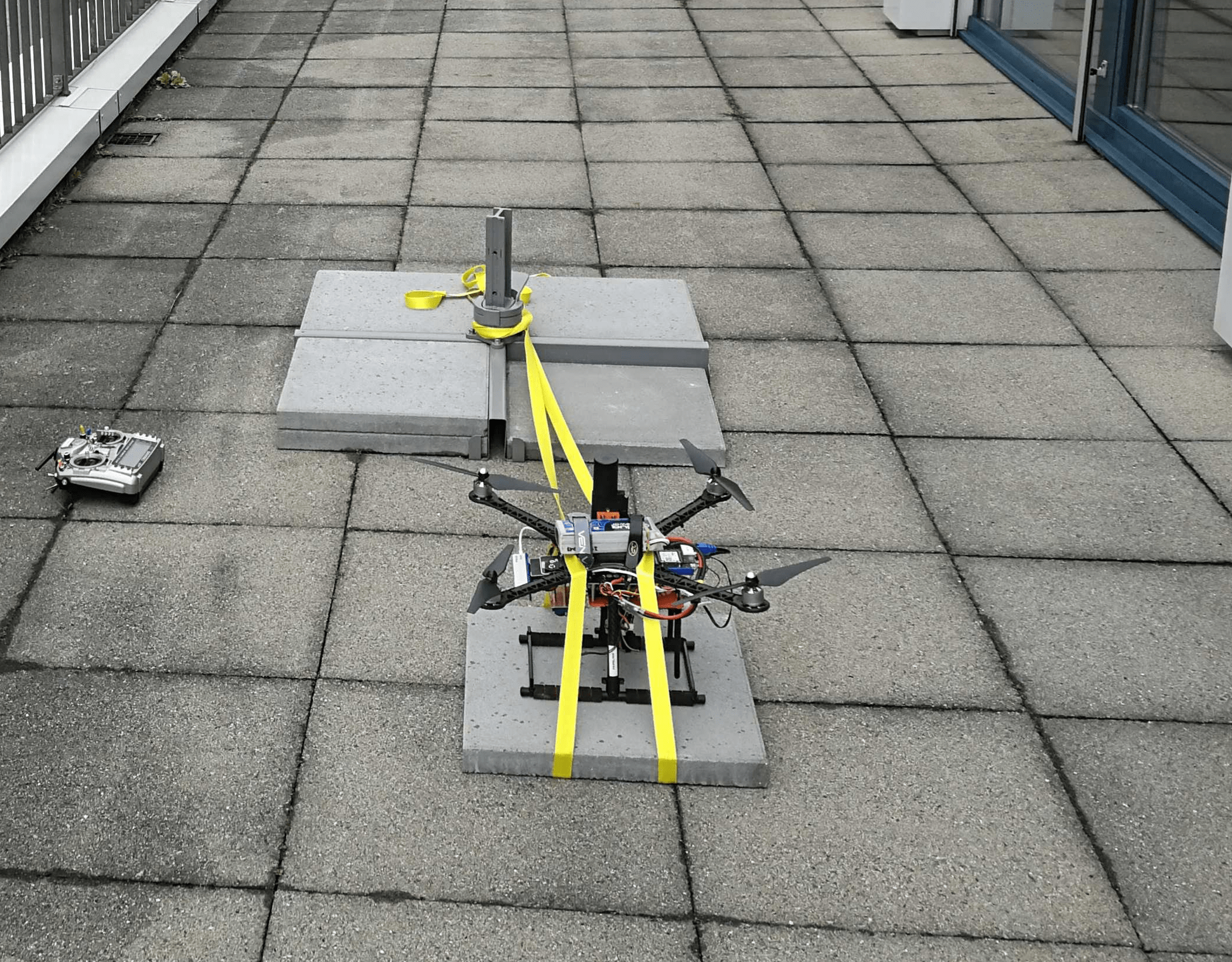
Secure the drone so that it cannot move, and attach the propellers (so the motors can draw the same current as in flight). This example secures the vehicle using straps.
Power the vehicle and switch into ACRO flight mode (using this mode ensures the vehicle won't attempt to compensate for movement resulting from the straps).
- Arm the vehicle and slowly raise the throttle to the maximum
- Slowly lower the throttle down to zero
- Disarm the vehicle
INFO
Perform the test carefully and closely monitor the vibrations.
Retrieve the ulog and use the python script mag_compensation.py to identify the compensation parameters.
shpython mag_compensation.py ~/path/to/log/logfile.ulg <type> [--instance <number>]where:
<type>:currentorthrust(power signal used for compensation)--instance <number>(optional): The number is0(default) or1, the instance of the current or thrust signal to use.
INFO
If your log does not contain battery current measurements, you will need to comment out the respective lines in the Python script, such that it does the calculation for thrust only.
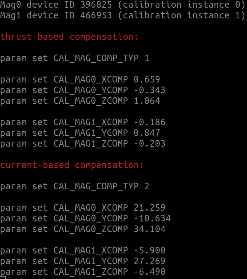
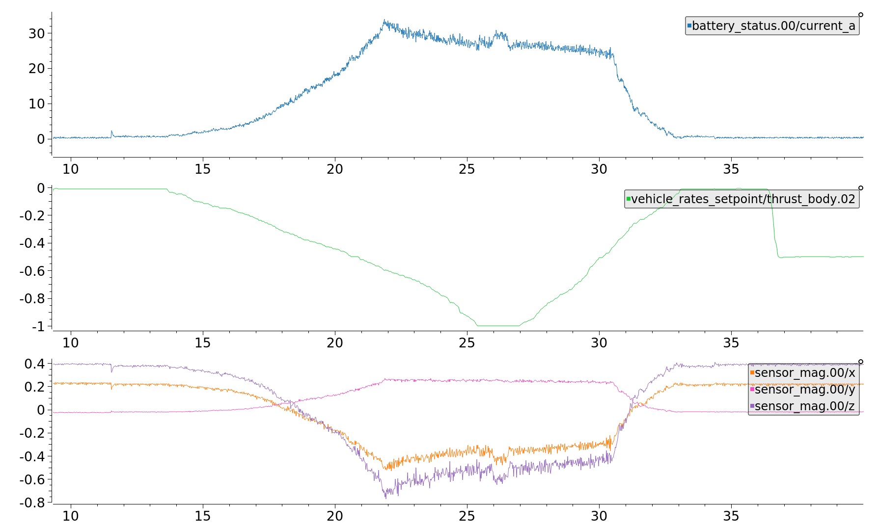
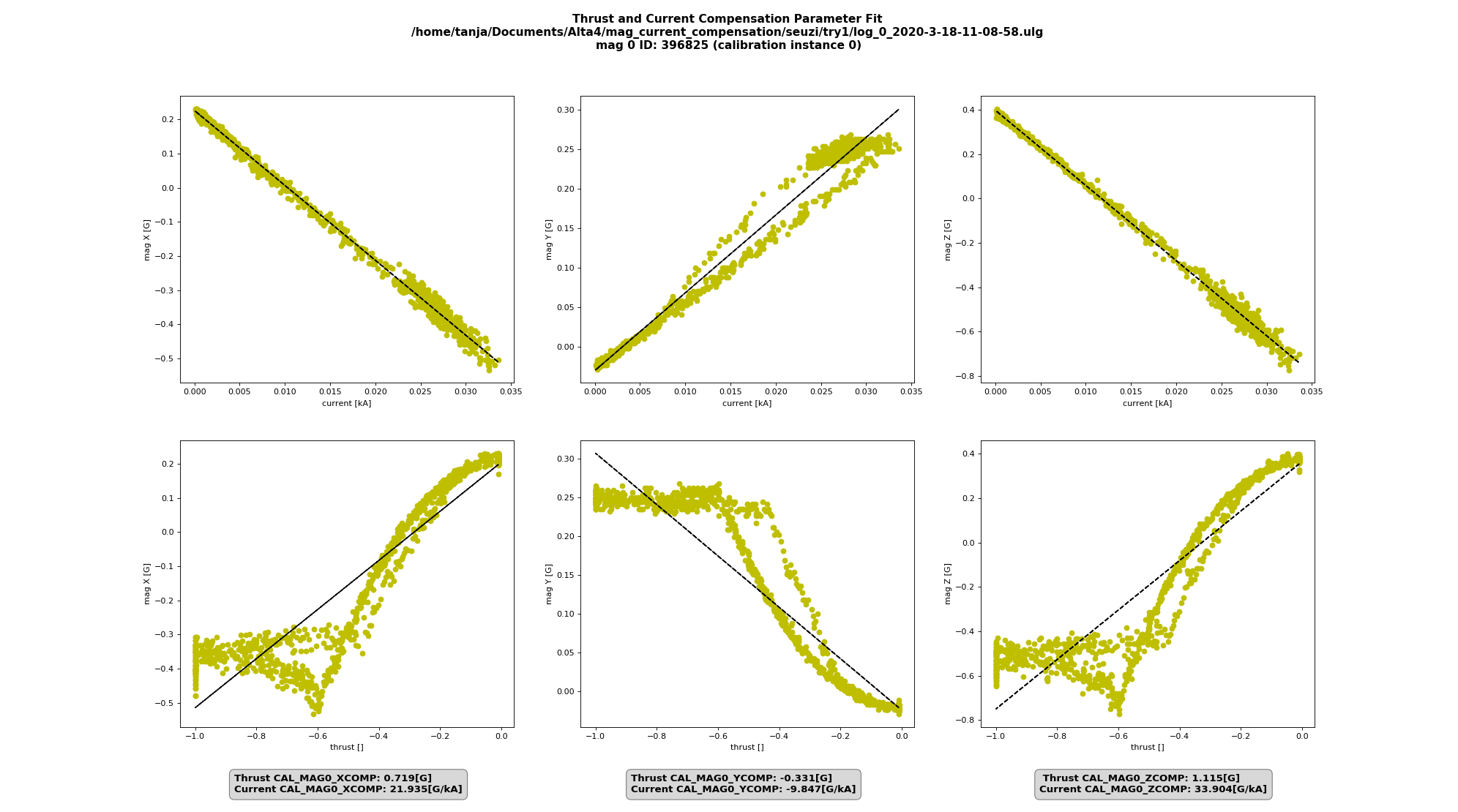
The script will return the parameter identification for thrust as well as for current and print them to the console. The figures that pop up from the script show the "goodness of fit" for each compass instance, and how the data would look if compensated with the suggested values. If a current measurement is available, using the current-compensation usually yields the better results. Here is an example of a log, where the current fit is good, but the thrust parameters are unusable as the relationship is not linear.
Once the parameters are identified, the power compensation must be enabled by setting CAL_MAG_COMP_TYP to 1 (when using thrust parameters) or 2 (when using current parameters). Additionally, the compensation parameters for each axis of each compass must be set.