Holybro Pixhawk 5X
WARNING
PX4 does not manufacture this (or any) autopilot. Contact the manufacturer for hardware support or compliance issues.
Pixhawk 5X® is the latest update to the successful family of Pixhawk® flight controllers designed and made in collaboration with Holybro® and the PX4 team.
It is based on the Pixhawk® Autopilot FMUv5X Standard, Autopilot Bus Standard, and Connector Standard. It comes with the latest PX4 Autopilot® pre-installed, triple redundancy, temperature-controlled, isolated sensor domain, delivering incredible performance and reliability.


TIP
This autopilot is supported by the PX4 maintenance and test teams.
Introduction
Inside the Pixhawk® 5X, you can find an STMicroelectronics® based STM32F7, paired with sensor technology from Bosch®, InvenSense®, giving you flexibility and reliability for controlling any autonomous vehicle, suitable for both academic and commercial applications. The Pixhawk® 5X’s F7 microcontroller has 2MB flash memory and 512KB RAM. The PX4 Autopilot takes advantage of the increased power and RAM. Thanks to the updated processing power, developers can be more productive and efficient with their development work, allowing for complex algorithms and models.
The FMUv5X open standard includes high-performance, low-noise IMUs on board, designed for better stabilization. Triple redundant IMU & double redundant barometer on separate buses. When the PX4 Autopilot detects a sensor failure, the system seamlessly switches to another to maintain flight control reliability.
An independent LDO powers every sensor set with independent power control. A newly designed vibration isolations to filter out high-frequency vibration and reduce noise to ensure accurate readings, allowing vehicles to reach better overall flight performances. External sensor bus (SPI5) has two chip select lines and data-ready signals for additional sensors and payload with SPI-interface, and with an integrated Microchip Ethernet PHY (LAN8742AI-CZ-TR), high-speed communication with mission computers via ethernet is now supported. Two smart battery monitoring ports (SMBus), support for INA226 SMBus Power module.
The Pixhawk® 5X is perfect for developers at corporate research labs, startups, academics (research, professors, students), and commercial application.
Key Design Points
- Modular flight controller
- separated IMU, FMU, and Base system connected by a 100-pin & a 50-pin Pixhawk® Autopilot Bus connector, designed for flexible and customizable systems
- Redundancy
- 3x IMU sensors & 2x Barometer sensors on separate buses, allowing parallel and continuous operation even in the event of a hardware failure
- Triple redundancy domains
- Completely isolated sensor domains with separate buses and separate power control
- Temperature-controlled IMUs
- Onboard IMU heating resistors, allowing optimum working temperature of IMUs
- Vibration isolation system
- Newly designed system to filter out high frequency vibration and reduce noise to ensure accurate readings
- Ethernet interface
- For high-speed mission computer integration
- Automated sensor calibration eliminating varying signals and temperature
- Two smart batteries monitoring on SMBus
- Additional GPIO line and 5V for the external NFC reader
- Secure element for secure authentication of the drone (SE050)
Technical specification
FMU Processor: STM32F765
- 32 Bit Arm® Cortex®-M7, 216MHz, 2MB memory, 512KB RAM
IO Processor: STM32F100
- 32 Bit Arm® Cortex®-M3, 24MHz, 8KB SRAM
On-board Sensors:
- Accel/Gyro: ICM-20649
- Accel/Gyro: ICM-42688P
- Accel/Gyro: ICM-20602
- Magnetometer: BMM150
- Barometer: 2x BMP388
Interfaces
- 16- PWM servo outputs
- R/C input for Spektrum / DSM
- Dedicated R/C input for PPM and S.Bus input
- Dedicated analog / PWM RSSI input and S.Bus output
- 4 general purpose serial ports
- 3 with full flow control
- 1 with separate 1.5A current limit
- 1 with I2C and additional GPIO line for external NFC reader
- 2 GPS ports
- 1 full GPS & Safety Switch Port
- 1 basic GPS port
- 1 I2C port
- 1 Ethernet port
- Transformerless Applications
- 100Mbps
- 1 SPI bus
- 2 chip select lines
- 2 data-ready lines
- 1 SPI SYNC line
- 1 SPI reset line
- 2 CAN Buses for CAN peripheral
- CAN Bus has individual silent controls or ESC RX-MUX control
- 2 Power input ports with SMBus
- 1 AD & IO port
- 2 additional analog input
- 1 PWM/Capture input
- 2 Dedicated debug and GPIO lines
Voltage Ratings
- Max input voltage: 6V
- USB Power Input: 4.75~5.25V
- Servo Rail Input: 0~36V
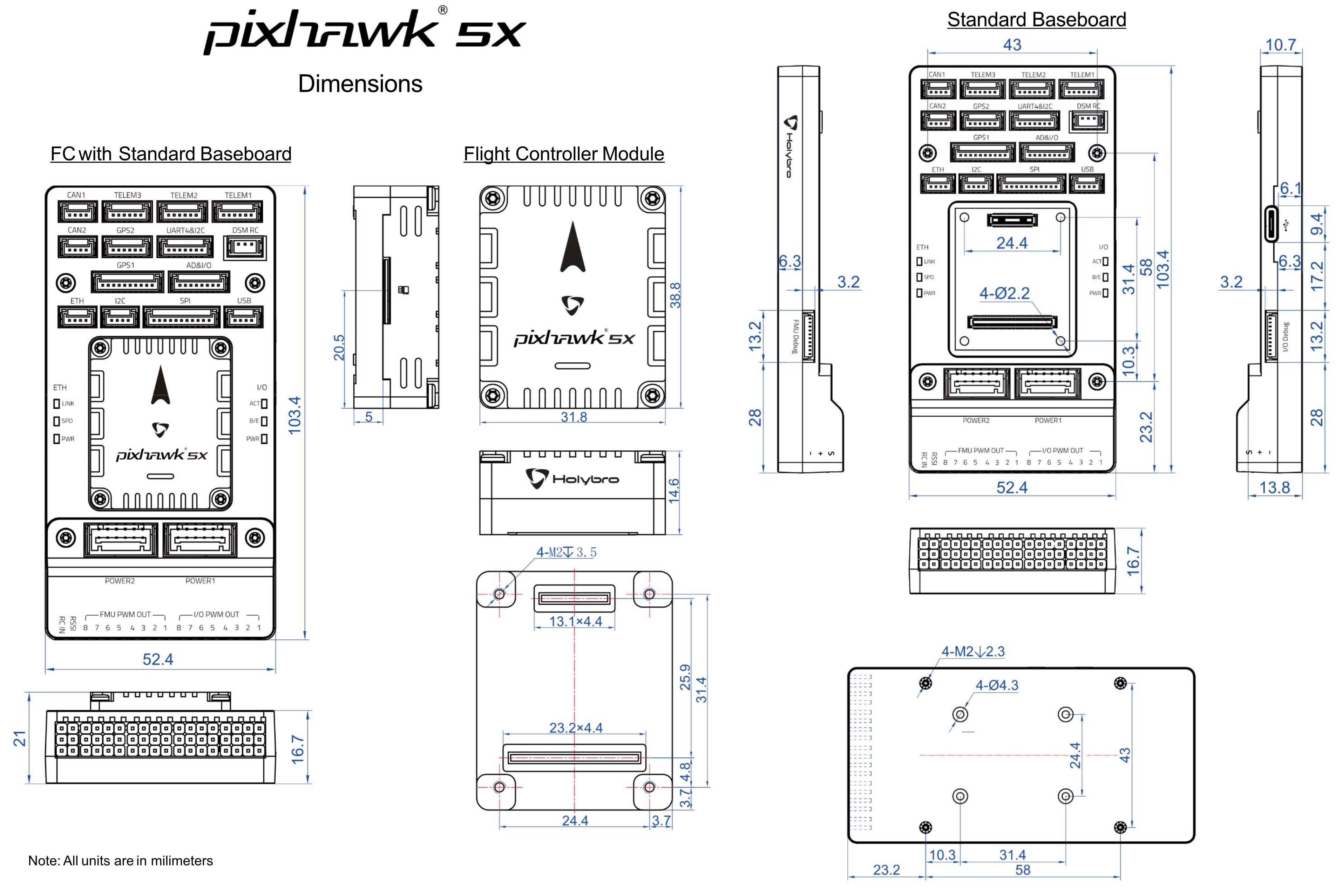
Dimensions
- Flight Controller Module: 38.8 x 31.8 x 14.6mm
- Standard Baseboard: 52.4 x 103.4 x 16.7mm
Weight
- Flight Controller Module: 23g
- Standard Baseboard: 51g
Other Characteristics:
- Operating & storage temperature: -40 ~ 85°c
Where to Buy
Order from Holybro.
Assembly/Setup
The Pixhawk 5X Wiring Quick Start provides instructions on how to assemble required/important peripherals including GPS, Power Module etc.
Connections
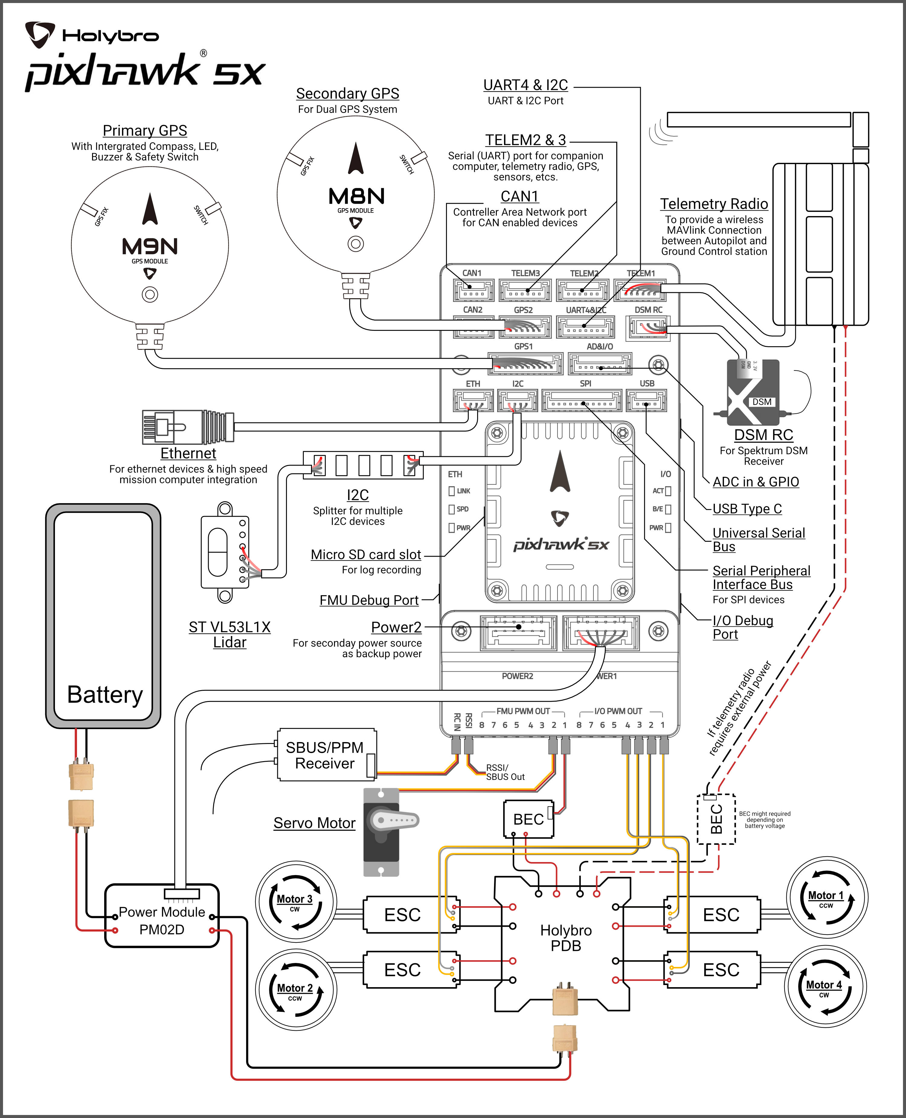
Pinouts
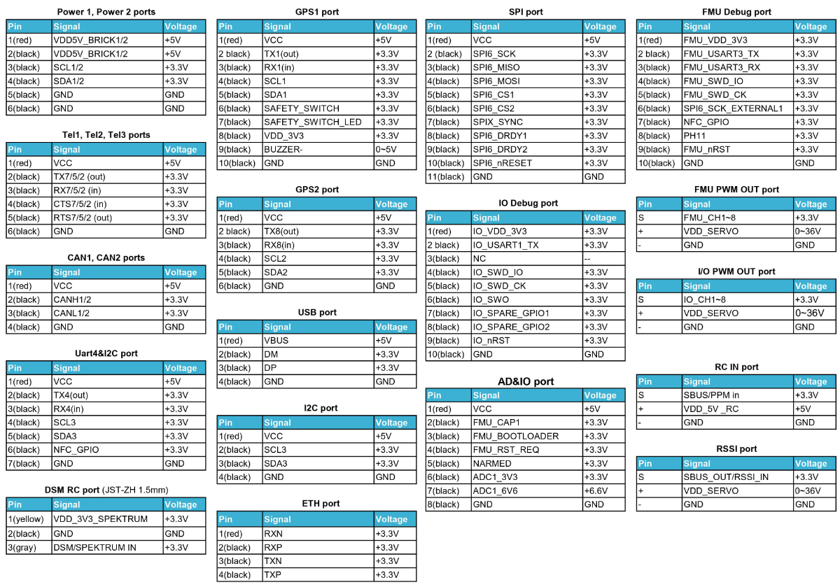
INFO
Connector pin assignments are left to right (i.e. Pin 1 is the left-most pin).
- The camera capture pin (
PI0) is pin 2 on the AD&IO port, marked above asFMU_CAP1. - Pixhawk 5X pinouts can be downloaded in PDF from here or here.
Serial Port Mapping
| UART | Device | Port |
|---|---|---|
| USART1 | /dev/ttyS0 | GPS |
| USART2 | /dev/ttyS1 | TELEM3 |
| USART3 | /dev/ttyS2 | Debug Console |
| UART4 | /dev/ttyS3 | UART4 & I2C |
| UART5 | /dev/ttyS4 | TELEM2 |
| USART6 | /dev/ttyS5 | PX4IO/RC |
| UART7 | /dev/ttyS6 | TELEM1 |
| UART8 | /dev/ttyS7 | GPS2 |
Dimensions
Voltage Ratings
Pixhawk 5X can be triple-redundant on the power supply if three power sources are supplied. The three power rails are: POWER1, POWER2 and USB. The POWER1 & POWER2 ports on the Pixhawk 5X uses the 6 circuit 2.00mm Pitch CLIK-Mate Wire-to-Board PCB Receptacle.
Normal Operation Maximum Ratings
Under these conditions all power sources will be used in this order to power the system:
- POWER1 and POWER2 inputs (4.9V to 5.5V)
- USB input (4.75V to 5.25V)
Absolute Maximum Ratings
Under these conditions the system will not draw any power (will not be operational), but will remain intact.
- POWER1 and POWER2 inputs (operational range 4.1V to 5.7V, 0V to 10V undamaged)
- USB input (operational range 4.1V to 5.7V, 0V to 6V undamaged)
- Servo input: VDD_SERVO pin of FMU PWM OUT and I/O PWM OUT (0V to 42V undamaged)
Voltage monitoring
Digital I2C battery monitoring is enabled by default (see Quickstart > Power).
INFO
Analog battery monitoring via an ADC is not supported on this particular board, but may be supported in variations of this flight controller with a different baseboard.
Building Firmware
TIP
Most users will not need to build this firmware! It is pre-built and automatically installed by QGroundControl when appropriate hardware is connected.
To build PX4 for this target:
make px4_fmu-v5x_defaultDebug Port
The PX4 System Console and SWD interface run on the FMU Debug port.
The pinouts and connector comply with the Pixhawk Debug Full interface defined in the Pixhawk Connector Standard interface (JST SM10B connector).
| Pin | Signal | Volt |
|---|---|---|
| 1 (red) | Vtref | +3.3V |
| 2 (blk) | Console TX (OUT) | +3.3V |
| 3 (blk) | Console RX (IN) | +3.3V |
| 4 (blk) | SWDIO | +3.3V |
| 5 (blk) | SWCLK | +3.3V |
| 6 (blk) | SWO | +3.3V |
| 7 (blk) | NFC GPIO | +3.3V |
| 8 (blk) | PH11 | +3.3V |
| 9 (blk) | nRST | +3.3V |
| 10 (blk) | GND | GND |
For information about using this port see:
- SWD Debug Port
- PX4 System Console (Note, the FMU console maps to USART3).
Peripherals
Supported Platforms / Airframes
Any multicopter / airplane / rover or boat that can be controlled with normal RC servos or Futaba S-Bus servos. The complete set of supported configurations can be seen in the Airframes Reference.