ThunderFly TFRPM01 Revolution Counter
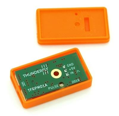
The TFRPM01 tachometer is a small, and low system demanding revolution-counter.
The board itself does not include the actual sensor but can be used with many different sensors/probe types for revolution counting. It has an I²C connector for connecting to PX4 and is connected to the actual sensor via a 3-pin connector. It also has an LED that offers basic diagnostic information.
INFO
The TFRPM01 sensor is open-source hardware commercially available from ThunderFly s.r.o. (manufacturing data is available on GitHub).
Hardware Setup
The board is equipped with (two through pass) I²C connectors for connecting to PX4 and has a 3-pin connector that can be used to connect to various sensors:
- TFRPM01 may be connected to any I²C port.
- TFRPM01 has a 3pin pin-header connector (with pull-up equipped input) that can be connected to different probe types.
- The sensor/probe hardware needs a pulse signal. The signal input accepts +5V TTL logic or open collector outputs. The maximum pulse frequency is 20 kHz with a 50% duty cycle.
- The probe connector provides a +5V power supply from the I²C bus, the maximum power which could be used is limited by RC filter (see schematics for details).
TFRPM01A electronics is equipped with signaling LED that can be used to check that the probe is connected properly. The LED lights up when the pulse input is grounded or exposed to logical 0, so you can check the probe is working correctly just by manually spinning a rotor.
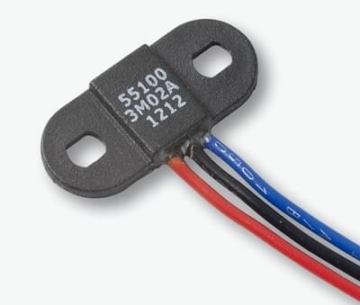
Hall-Effect Sensor Probe
Hall-Effect sensors (magnetically operated) are ideal for harsh environments, where dirt, dust, and water can contact the sensed rotor.
Many different hall effect sensors are commercially available. For example, a 55100 Miniature Flange Mounting Proximity Sensor is a good choice.
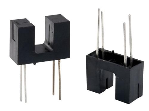
Optical Sensor Probe
An optical sensor can also be used (and may be a better fit, depending on the measurement requirements). Both transmissive and reflective sensor types may be used for pulse generation.
Software Setup
Starting driver
The driver is not started automatically (in any airframe). You will need to start it manually, either using the QGroundControl MAVLink Console or by adding the driver to the startup script on an SD card.
Start driver from console
Start the driver from the console using the command:
pcf8583 start -X -b <bus number>where:
-Xmeans that it is an external bus.<bus number>is the bus number to which the device is connected
INFO
The bus number in code -b <bus number> may not match the bus labels on the autopilot. For example, when using CUAV V5+ or CUAV Nano:
| Autopilot label | -b number |
|---|---|
| I2C1 | -X -b 4 |
| I2C2 | -X -b 2 |
| I2C3 | -X -b 1 |
The pcf8583 start command outputs the corresponding autopilot bus name/label for each bus number.
Testing
You can verify the counter is working using several methods
PX4 (NuttX) MAVLink Console
The QGroundControl MAVLink Console can also be used to check that the driver is running and the UORB topics it is outputting.
To check the status of the TFRPM01 driver run the command:
pcf8583 statusIf the driver is running, the I²C port will be printed along with other basic parameters of the running instance. If the driver is not running it can be started using theprocedure described above.
The listener command allows you to monitor RPM UORB messages from the running driver.
listener rpmFor periodic display, you can add -n 50 parameter after the command, which prints the next 50 messages.
QGroundControl MAVLink Inspector
The QGroundControl Mavlink Inspector can be used to observe MAVLink messages from PX4, including RAW_RPM emitted by the driver:
- Start the inspector from the QGC menu: Analyze tools > Mavlink Inspector
- Check that
RAW_RPMis present in the list of messages (if it is missing, check that the driver is running).
Parameter Setup
Usually, sensors can be used without configuration, but the RPM values should correspond to multiples of real RPM. It is because the PCF8583_MAGNET parameter needs to correspond to the real number of pulses per single revolution of the sensed rotor. If needed, the following parameters should be tweaked:
- PCF8583_POOL — pooling interval between readout the counted number
- PCF8583_RESET — Counter value where the counted number should be reset to zero.
- PCF8583_MAGNET — Number of pulses per revolution e.g. number of magnets at a rotor disc.
INFO
The parameters above appear in QGC after the driver/PX4 are restarted.
If the configuration parameters are not available after restart then you should check that the driver has started. It may be that the driver is not present in the firmware, in which case it must be added to the board configuration:
drivers/rpm/pcf8583