CUAV Pixhawk V6X Wiring Quick Start
This quick start guide shows how to power the Pixhawk V6X® flight controller and connect its most important peripherals.
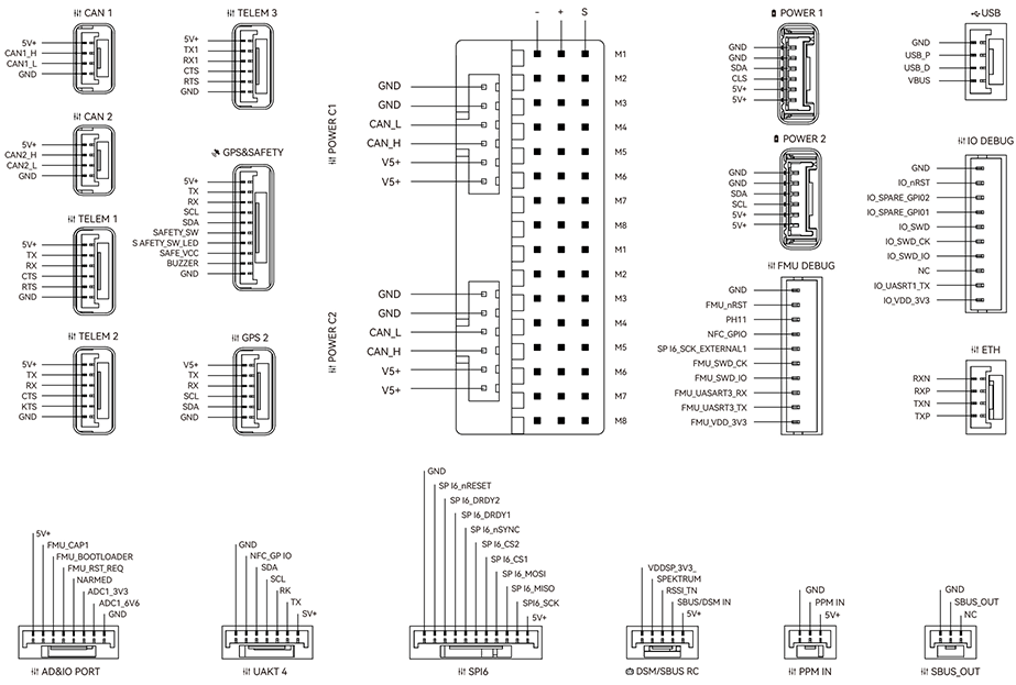
Wiring Chart Overview
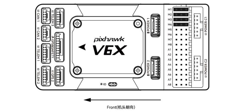
The image below shows how to connect the most important sensors and peripherals (except the motor and servo outputs). We'll go through each of these in detail in the following sections.
| Interface | Function |
|---|---|
| POWER C1 | Connect CAN PMU SE to this interface; this interface is connected to UAVCAN power module |
| POWER C2 | Connect CAN PMU SE to this interface; this interface is connected to UAVCAN power module |
| POWER 1 | Connect SMbus (I2C) power module |
| POWER 2 | Connect SMbus (I2C) power module |
| GPS&SAFETY | Connect Neo series GPS/C-RTK 9PS, including GPS, safety switch, buzzer interface. |
| GPS2 | Connect GPS/RTK module |
| UART 4 | User customizable |
| TELEM (1,2,3) | Connect telemetry or MAVLink devices |
| TF CARD | SD card for log storage (card pre-inserted in factory). |
| M1~M8 | IO PWM output (for connecting to ESC and Servo) |
| A1~A8 | FMU PWM output. Can be defined as PWM/GPIO; supports dshot; used to connect camera shutter/hot shoe, servo, etc. |
| USB | Connect to a computer for communication between the flight controller and the computer, such as loading firmware. |
| CAN1/CAN2 | Connect Dronecan/UAVCAN devices such as NEO3 Pro. |
| DSM/SUB/RSSI | Includes DSM, SBUS, RSSI signal input interface, DSM interface can be connected to DSM satellite receiver, SBUS interface to SBUS remote control receiver, RSSI for signal strength return module |
| PPM | Connecting the PPM RC Receiver |
| ETH | Ethernet interface. Connect Ethernet devices such as task computers |
| AD&IO | There are two analog inputs (ADC3.3/ADC6.6); generally not used |
Vehicle Front
INFO
If the controller cannot be mounted in the recommended/default orientation (e.g. due to space constraints) you will need to configure the autopilot software with the orientation that you actually used: Flight Controller Orientation.
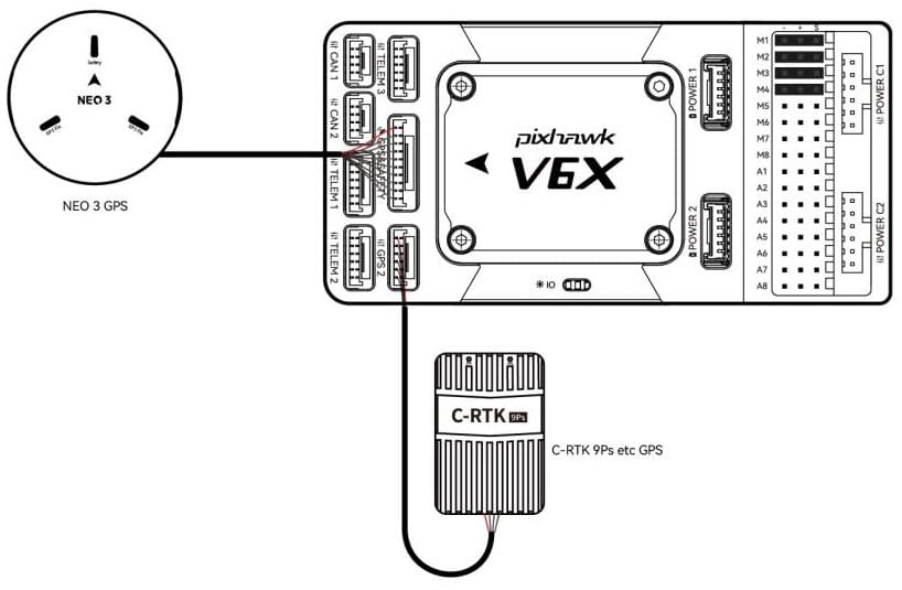
GPS + Compass + Buzzer + Safety Switch + LED
The Pixhawk® V6X can be purchased with a NEO3 GPS (10-pin connector) and should be connected to the GPS1 port. These GNSS modules feature an integrated compass, safety switch, buzzer and LEDs.
If you need to use assisted GPS, connect to the GPS2 port.
The GPS/compass should be mounted on the frame as far away from other electronics as possible, with the direction markings towards the front of the vehicle (separating the compass from other electronics will reduce interference).
INFO
Pixhawk V6X® is not compatible with NEO V2 GPS built-in buzzer: you should use NEO3/NEO 3Pro instead. The GPS module's integrated safety switch is enabled by default (when enabled, PX4 will not let you arm the vehicle). To disable the safety press and hold the safety switch for 1 second. You can press the safety switch again to enable safety and disarm the vehicle (this can be useful if, for whatever reason, you are unable to disarm the vehicle from your remote control or ground station).
Radio Control
A remote control (RC) radio system is required if you want to manually control your vehicle (PX4 does not require a radio system for autonomous flight modes).
You will need to select a compatible transmitter/receiver and then bind them so that they communicate (read the instructions that come with your specific transmitter/receiver).
- Spektrum/DSM receivers connect to the DSM/SBUS input.
- PPM receivers connect to the PPM input port.
For more information about selecting a radio system, receiver compatibility, and binding your transmitter/receiver pair, see: Remote Control Transmitters & Receivers.
Power
Pixhawk V6X® is equipped with a CAN PMU lite module that supports 3~14s lithium battery. Connect the 6pin connector of the module to the flight control Power C1 or Power C2 interface.
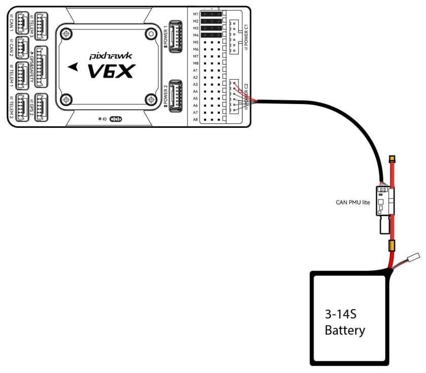
Pixhawk V6X power port receives Dronecan digital signal from CAN PMU lite power module for voltage, current and remaining battery data, the VCC line must provide at least 3A continuous current and should default to 5.2V. A lower voltage of 5V is still acceptable but discouraged.
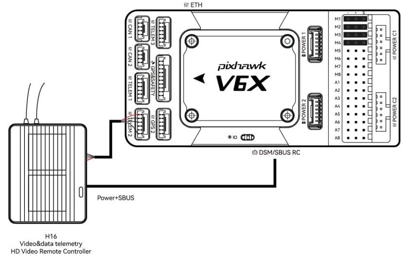
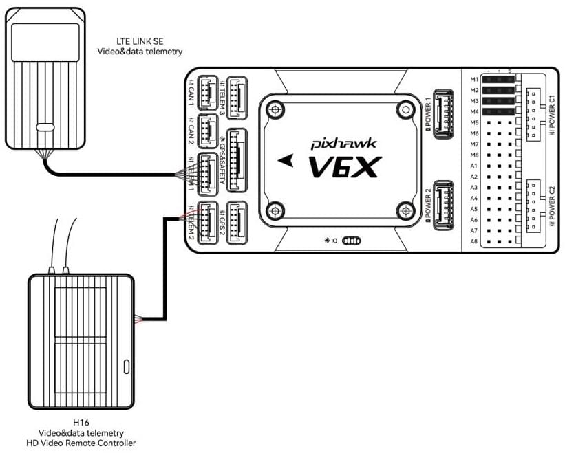
Telemetry (Radio) System
Telemetry radios may be used to communicate and control a vehicle in flight from a ground station (for example, you can direct the UAV to a particular position, or upload a new mission).
The vehicle-based radio should be connected to the TELEM1/TELEM2/TELEM3 port as shown below (if connected to TELEM1, no further configuration is required). The other radio is connected to your ground station computer or mobile device (usually by USB).
You can also purchase telemetry radios from the CUAV store.
SD Card
SD cards are highly recommended as they are required for recording and analyzing flight details, running tasks and using UAVCAN bus hardware. An SD card is already installed on Pixhawk V6X® when it leaves the factory.
TIP
For more information see Basic Concepts > SD Cards (Removable Memory).
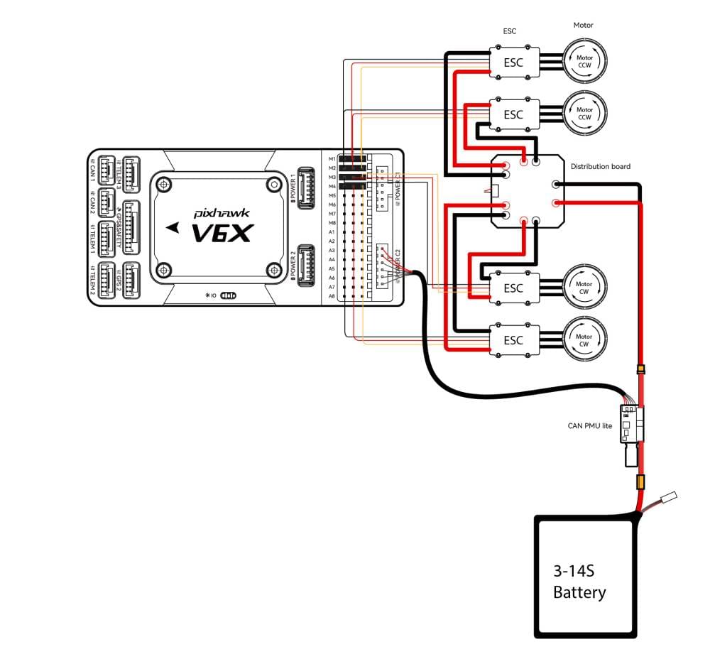
Motors/Servo
Motors/servos are connected to the M1~M8 (MAIN) and A1~A8 (AUX) ports in the order specified for your vehicle in the Airframe Reference.
INFO
The MAIN outputs in the PX4 firmware are mapped to the Pixhawk V6X's M1~M8 ports (from IO), while the AUX outputs are mapped to the A1~A8 ports (from the FMU). For example, MAIN1 maps to M1 pin and AUX1 maps to A1 pin. This reference lists the output port to motor/servo mapping for all supported air and ground frames (if your frame is not listed in the reference then use a "generic" airframe of the correct type).
WARNING
The mapping is not consistent across frames (e.g. you can't rely on the throttle being on the same output for all plane frames). Make sure to use the correct mapping for your vehicle.
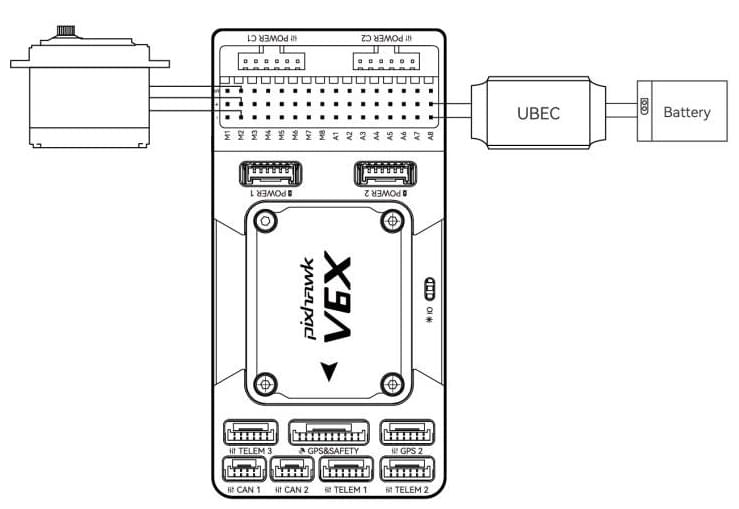
Servo Power Supply
Pixhawk V6X® does not supply power to the servos. If using a plane or rover, an external BEC (e.g., BEC-equipped ESC or separate 5V BEC or 2S LiPo battery) needs to be connected to any of the power (+) pins in M1~M8/A1~A8 to drive the servos .
INFO
The power rail voltage must be appropriate for the servo being used!
Other Peripherals
The wiring and configuration of optional/less common components is covered within the topics for individual peripherals.
Pinouts
Configuration
General configuration information is covered in: Autopilot Configuration.
QuadPlane specific configuration is covered here: QuadPlane VTOL Configuration
Further information
- CUAV Docs (CUAV)
- Pixhawk V6X (PX4 Doc Overview page)
- Pixhawk Autopilot FMUv6X Standard
- Pixhawk Autopilot Bus Standard
- Pixhawk Connector Standard