Holybro Pixhawk 6X Pro
WARNING
PX4 does not manufacture this (or any) autopilot. Contact the manufacturer for hardware support or compliance issues.
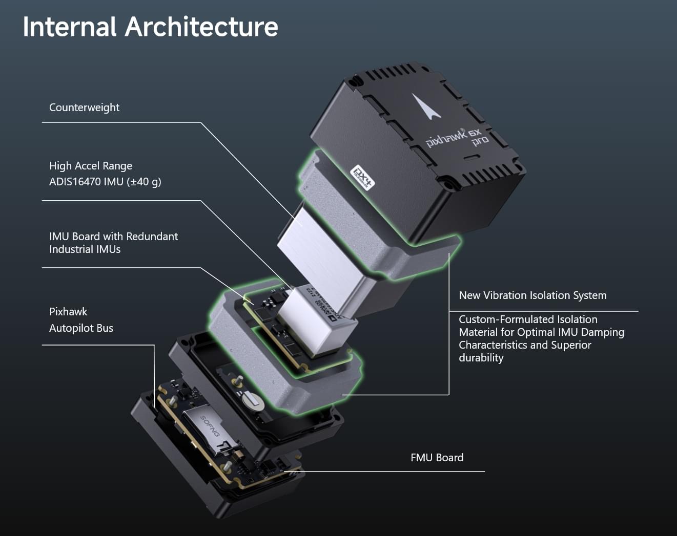
Key Design Points
- High-performance ADIS16470 Industrial IMU with high accelerometer dynamic range (±40 g), perfect for accurate motion sensing in demanding UAV applications
- All new advanced durable vibration isolation material with resonance frequency in the higher spectrum, ideal for industrial and commercial drone applications
- High performance STM32H753 Processor
- Ethernet interface for high-speed mission computer integration
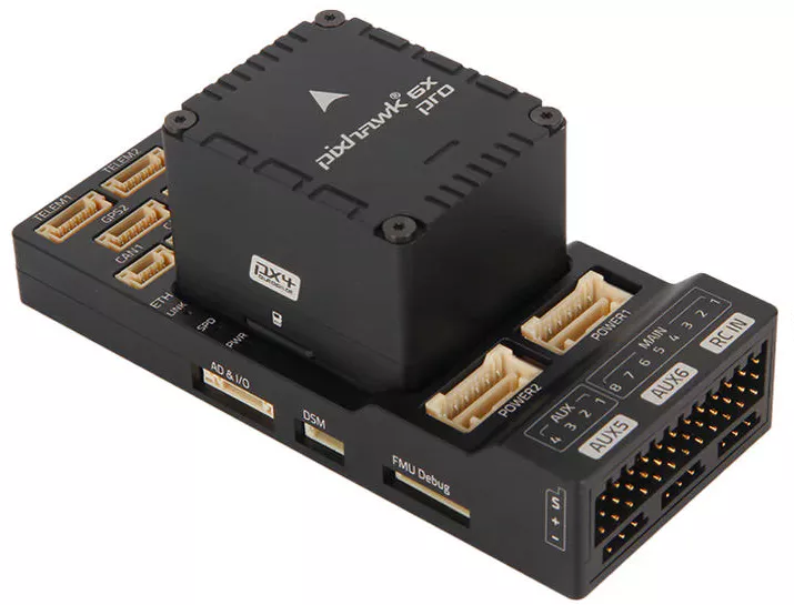
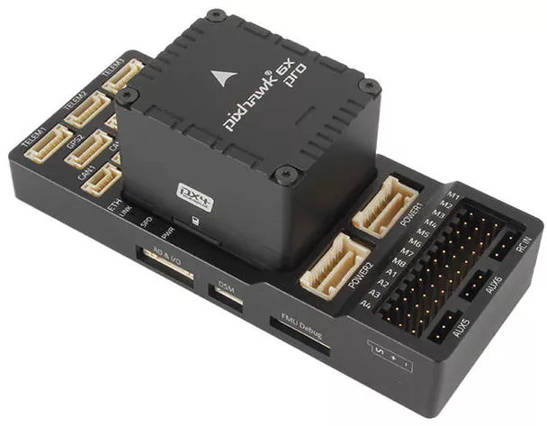
Baseboards
The Pixhawk 6X Pro can be purchased with a number of baseboards (or no baseboard) to suit different use cases and vehicle types, including Standard v2A, Standard v2B, and Mini, which are shown below. It can also be used with any other Pixhawk Autopilot Bus (PAB) specification-compliant baseboard, such as the Holybro Pixhawk Jetson Baseboard and Holybro Pixhawk RPi CM4 Baseboard.
Features
- Triple redundant IMU & double redundant barometer on separate buses
- Modular flight controller: separated IMU, FMU, and Base system
- Safety-driven design incorporates sensors from different manufacturers and model lineups
- Independent LDO powers every sensor set with independent power control.
- Temperature-controlled IMU board, allowing optimum working temperature of IMUs
Processors & Sensors
- FMU Processor: STM32H753
- 32 Bit Arm® Cortex®-M7, 480MHz, 2MB flash memory, 1MB RAM
- IO Processor: STM32F103
- 32 Bit Arm® Cortex®-M3, 72MHz, 64KB SRAM
- On-board sensors
- Accel/Gyro: ADIS16470 (±40g, Vibration Isolated, Industrial IMU)
- Accel/Gyro: IIM-42652 (±16g, Vibration Isolated, Industrial IMU)
- Accel/Gyro: ICM-45686 with BalancedGyro™ Technology (±32g, Hard Mounted)
- Barometer: ICP20100
- Barometer: BMP388
- Mag: BMM150
Electrical data
- Voltage Ratings:
- Max input voltage: 6V
- USB Power Input: 4.75~5.25V
- Servo Rail Input: 0~36V
- Current Ratings: - Telem1 output current limiter: 1.5A - All other port combined output current limiter: 1.5A
Mechanical data
- Dimensions
- Flight Controller Module: 38.8 x 31.8 x 30.1mm
- Standard Baseboard: 52.4 x 103.4 x 16.7mm
- Mini Baseboard: 43.4 x 72.8 x 14.2 mm
- Weight - Flight Controller Module: 50g - Standard Baseboard: 51g - Mini Baseboard: 26.5g
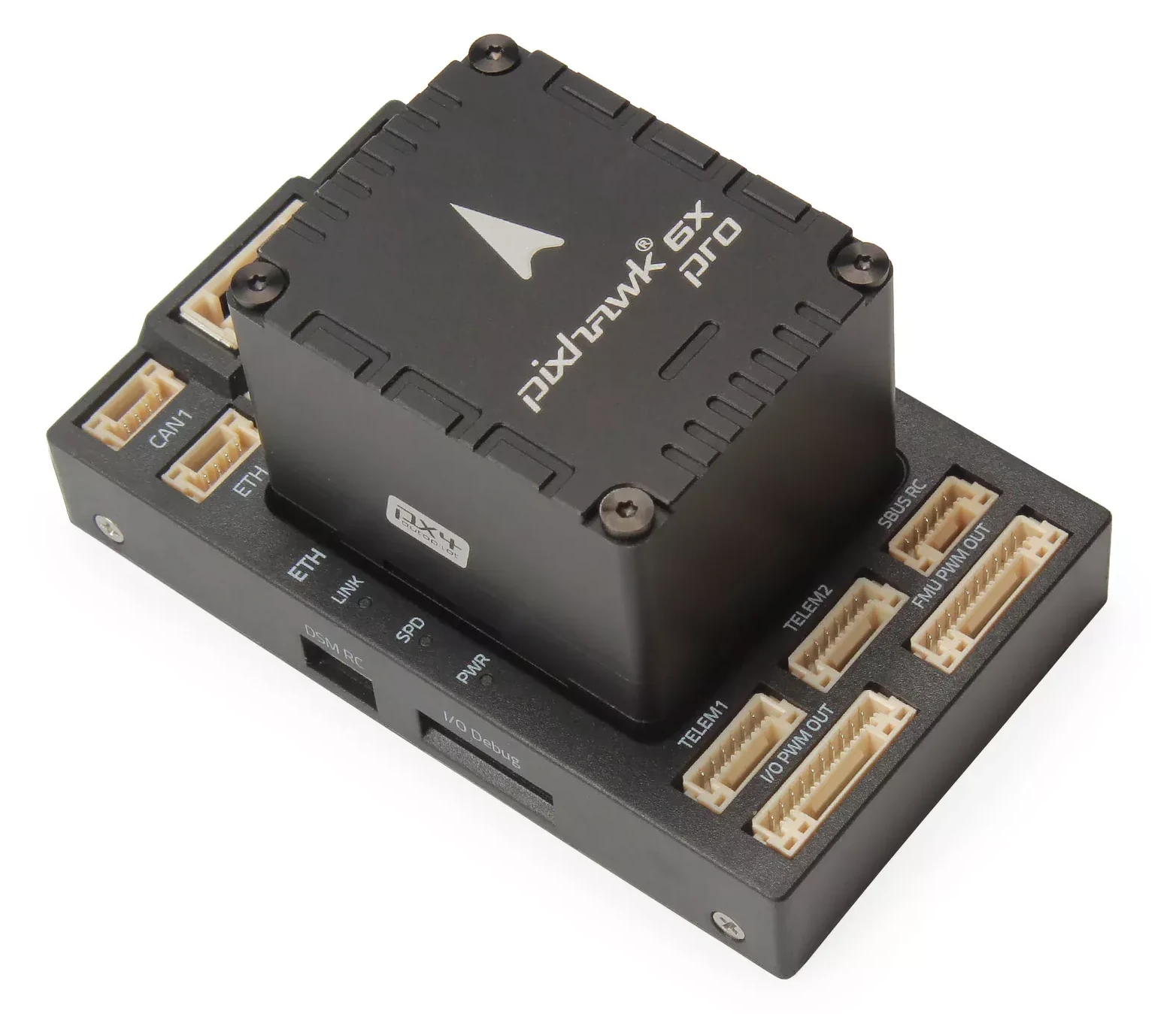
Interfaces
- 16- PWM servo outputs
- R/C input for Spektrum / DSM
- Dedicated R/C input for PPM and S.Bus input
- Dedicated analog / PWM RSSI input and S.Bus output
- 4 general purpose serial ports
- 3 with full flow control
- 1 with separate 1.5A current limit (Telem1)
- 1 with I2C and additional GPIO line for external NFC reader
- 2 GPS ports
- 1 full GPS plus Safety Switch Port
- 1 basic GPS port
- 1 I2C port
- 1 Ethernet port
- Transformerless Applications
- 100Mbps
- 1 SPI bus
- 2 chip select lines
- 2 data-ready lines
- 1 SPI SYNC line
- 1 SPI reset line
- 2 CAN Buses for CAN peripheral
- CAN Bus has individual silent controls or ESC RX-MUX control
- 2 Power input ports with SMBus - 1 AD & IO port - 2 additional analog input - 1 PWM/Capture input - 2 Dedicated debug and GPIO lines
Where to Buy
Order from Holybro.
Assembly/Setup
The Pixhawk 6X Wiring Quick Start provides instructions on how to assemble required/important peripherals including GPS, Power Module etc.
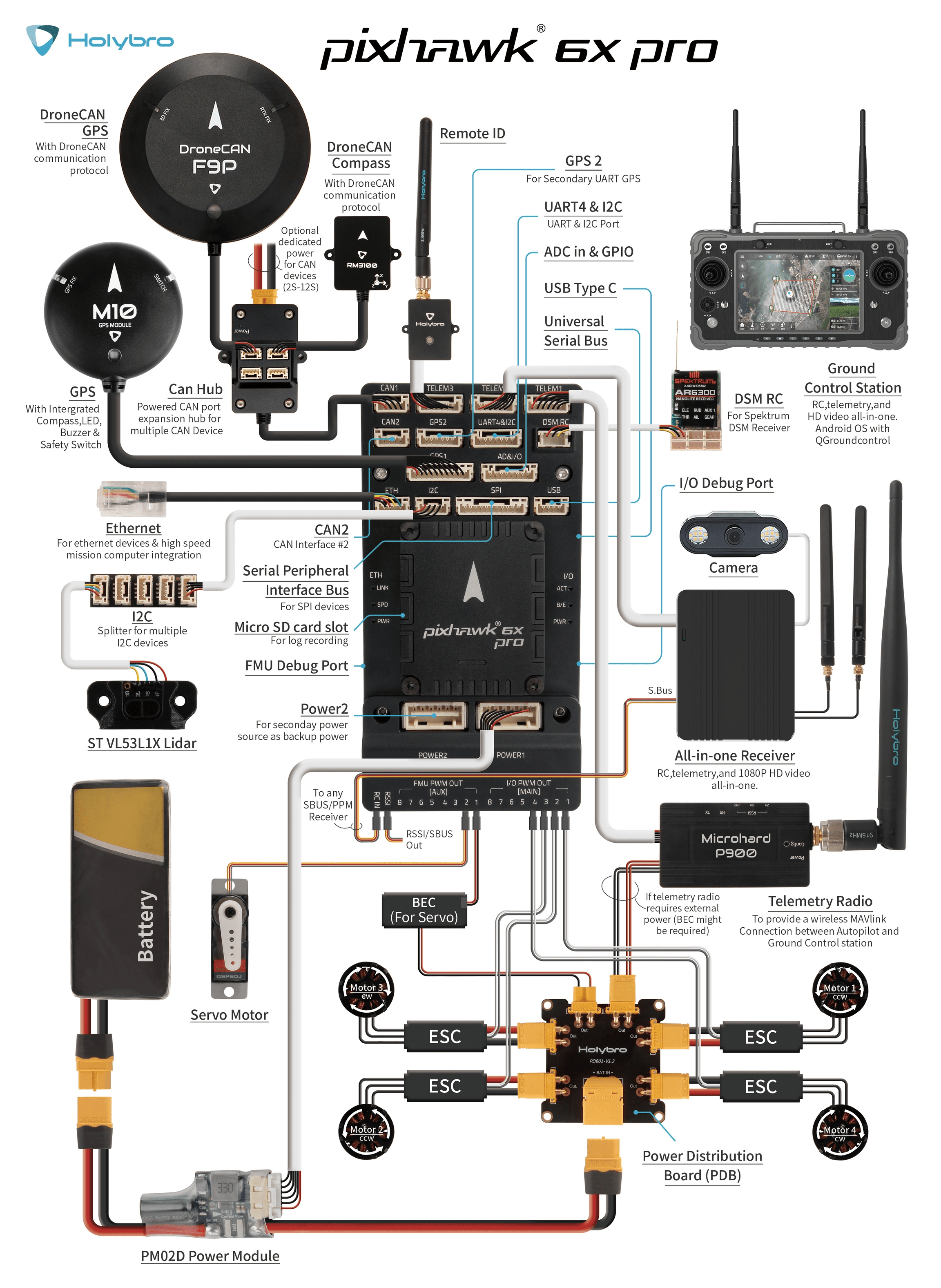
Connections
Multicopter Wiring Example
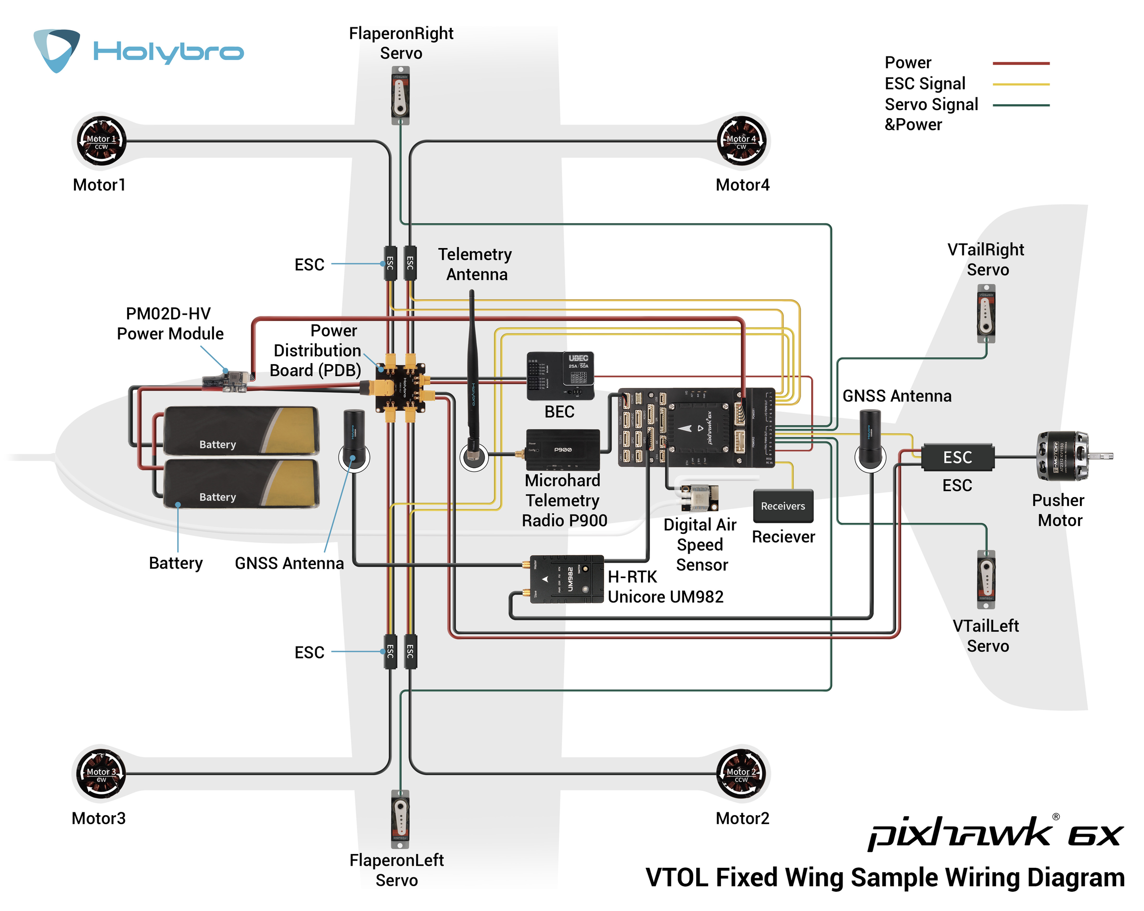
VTOL Wiring Example
Pinouts
- Holybro Pixhawk Baseboard Pinout
- Holybro Pixhawk Mini-Baseboard Pinout
- Holybro Pixhawk Jetson Baseboard
- Holybro Pixhawk RPi CM4 Baseboard
Notes:
- The camera capture pin (
PI0) is pin 2 on the AD&IO port, marked above asFMU_CAP1.
Serial Port Mapping
| UART | Device | Port |
|---|---|---|
| USART1 | /dev/ttyS0 | GPS |
| USART2 | /dev/ttyS1 | TELEM3 |
| USART3 | /dev/ttyS2 | Debug Console |
| UART4 | /dev/ttyS3 | UART4 & I2C |
| UART5 | /dev/ttyS4 | TELEM2 |
| USART6 | /dev/ttyS5 | PX4IO/RC |
| UART7 | /dev/ttyS6 | TELEM1 |
| UART8 | /dev/ttyS7 | GPS2 |
Dimensions
Voltage Ratings
Pixhawk 6X Pro can be triple-redundant on the power supply if three power sources are supplied. The three power rails are: POWER1, POWER2 and USB. The POWER1 & POWER2 ports on the Pixhawk 6X uses the 6 circuit 2.00mm Pitch CLIK-Mate Wire-to-Board PCB Receptacle.
Normal Operation Maximum Ratings
Under these conditions all power sources will be used in this order to power the system:
- POWER1 and POWER2 inputs (4.9V to 5.5V)
- USB input (4.75V to 5.25V)
Absolute Maximum Ratings
Under these conditions the system will not draw any power (will not be operational), but will remain intact.
- POWER1 and POWER2 inputs (operational range 4.1V to 5.7V, 0V to 10V undamaged)
- USB input (operational range 4.1V to 5.7V, 0V to 6V undamaged)
- Servo input: VDD_SERVO pin of FMU PWM OUT and I/O PWM OUT (0V to 42V undamaged)
Voltage monitoring
Digital I2C battery monitoring is enabled by default (see Quickstart > Power).
INFO
Analog battery monitoring via an ADC is not supported on this particular board, but may be supported in variations of this flight controller with a different baseboard.
Building Firmware
TIP
Most users will not need to build this firmware! It is pre-built and automatically installed by QGroundControl when appropriate hardware is connected.
To build PX4 for this target:
sh
make px4_fmu-v6x_defaultDebug Port
The PX4 System Console and SWD interface run on the FMU Debug port.
The pinouts and connector comply with the Pixhawk Debug Full interface defined in the Pixhawk Connector Standard interface (JST SM10B connector).
| Pin | Signal | Volt |
|---|---|---|
| 1 (red) | Vtref | +3.3V |
| 2 (blk) | Console TX (OUT) | +3.3V |
| 3 (blk) | Console RX (IN) | +3.3V |
| 4 (blk) | SWDIO | +3.3V |
| 5 (blk) | SWCLK | +3.3V |
| 6 (blk) | SWO | +3.3V |
| 7 (blk) | NFC GPIO | +3.3V |
| 8 (blk) | PH11 | +3.3V |
| 9 (blk) | nRST | +3.3V |
| 10 (blk) | GND | GND |
For information about using this port see:
- SWD Debug Port
- PX4 System Console (Note, the FMU console maps to USART3).
Peripherals
- Telemetry Radio Modules
- Rangefinders/Distance sensors
- Holybro Sensors
- Holybro GPS & RTK Systems
- Power Modules & PDBs
Supported Platforms/Airframes
Any multicopter / airplane / rover or boat that can be controlled with normal RC servos or Futaba S-Bus servos. The complete set of supported configurations can be seen in the Airframes Reference.
CAD File
Download here.