Visual Inertial Odometry (VIO)
Visual Inertial Odometry (VIO) is a computer vision technique used for estimating the 3D pose (local position and orientation) and velocity of a moving vehicle relative to a local starting position. It is commonly used to navigate a vehicle in situations where GPS is absent or unreliable (e.g. indoors, or when flying under a bridge).
VIO uses Visual Odometry to estimate vehicle pose from camera images, combined with inertial measurements from the vehicle IMU (to correct for errors associated with rapid vehicle movement resulting in poor image capture).
This topic gives guidance on configuring PX4 and a companion computer for a VIO setup.
INFO
The suggested setup uses ROS for routing VIO information to PX4. However, PX4 itself does not care about the source of messages, provided they are provided via the appropriate MAVLink Interface.
Suggested Setup
A hardware and software setup for VIO is suggested in the sections below as an illustration of how to interface a VIO system with PX4. It makes use of an off-the-shelf tracking camera and a companion computer running ROS. ROS is used to read odometry information from the camera and supply it to PX4.
An example of a suitable tracking camera is the Intel® RealSense™ Tracking Camera T265.
Camera Mounting
Attach the camera to the companion computer and mount it to the frame:
- Mount the camera with lenses pointing down if at all possible (default).
- Cameras are typically very sensitive to vibration; a soft mounting is recommended (e.g. using vibration isolation foam).
Companion Setup
To setup ROS and PX4:
On the companion computer, install and configure MAVROS.
Implement and run a ROS node to read data from the camera and publish the VIO odometry using MAVROS.
- See the VIO ROS node section below for details of the requirements for this node.
Follow the instructions below for tuning the PX4 EKF2 estimator.
Verify the connection to the flight controller.
TIP
You can use the QGroundControl MAVLink Inspector to verify that you're getting
ODOMETRYorVISION_POSITION_ESTIMATEmessages (or check forHEARTBEATmessages that have the component id 197 (MAV_COMP_ID_VISUAL_INERTIAL_ODOMETRY)).Verify that VIO is set up correctly before your first flight!
ROS VIO node
In this suggested setup, a ROS node is required to
- interface with the chosen camera or sensor hardware,
- produce odometry messages containing the position estimate, which will be sent to PX4 using MAVROS, and
- publish messages to indicate the VIO system status.
The implementation of the ROS node will be specific to the camera used and will need to be developed to use the interface and drivers appropriate for the camera.
The odometry messages should be of the type nav_msgs/Odometry and published to the topic /mavros/odometry/out.
System status messages of the type mavros_msgs/CompanionProcessStatus should be published to the topic /mavros/companion_process/status. These should identify the component as MAV_COMP_ID_VISUAL_INERTIAL_ODOMETRY (197) and indicate the state of the system. Recommended status values are:
MAV_STATE_ACTIVEwhen the VIO system is functioning as expected,MAV_STATE_CRITICALwhen the VIO system is functioning, but with low confidence, andMAV_STATE_FLIGHT_TERMINATIONwhen the system has failed or the estimate confidence is unacceptably low.
PX4 Tuning
The following parameters must be set to use external position information with EKF2.
| Parameter | Setting for External Position Estimation |
|---|---|
| EKF2_EV_CTRL | Set horizontal position fusion, vertical vision fusion, velocity fusion, and yaw fusion according to your desired fusion model. |
| EKF2_HGT_REF | Set to Vision to use the vision as the reference sensor for altitude estimation. |
| EKF2_EV_DELAY | Set to the difference between the timestamp of the measurement and the "actual" capture time. For more information see below. |
| EKF2_EV_POS_X, EKF2_EV_POS_Y, EKF2_EV_POS_Z | Set the position of the vision sensor with respect to the vehicle's body frame. |
These can be set in QGroundControl > Vehicle Setup > Parameters > EKF2 (remember to reboot the flight controller in order for parameter changes to take effect).
For more detailed/additional information, see: Using PX4's Navigation Filter (EKF2) > External Vision System.
Tuning EKF2_EV_DELAY
EKF2_EV_DELAY is the Vision Position Estimator delay relative to IMU measurements. In other words, it is the difference between the vision system timestamp and the "actual" capture time that would have been recorded by the IMU clock (the "base clock" for EKF2).
Technically this can be set to 0 if there is correct timestamping (not just arrival time) and timesync (e.g. NTP) between MoCap and (for example) ROS computers. In reality, this may need some empirical tuning because delays in the communication chain are very setup-specific. It is rare that a system is set up with an entirely synchronised chain!
A rough estimate of the delay can be obtained from logs by checking the offset between IMU rates and the EV rates:
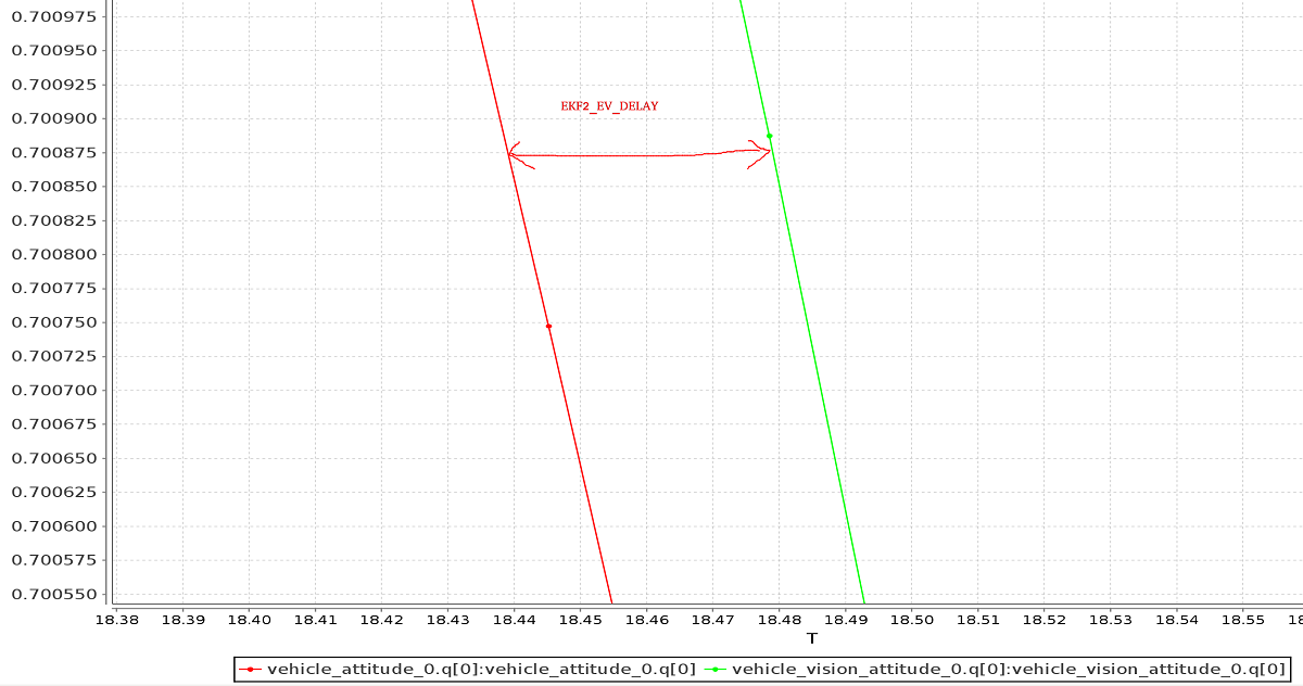
INFO
A plot of external data vs. onboard estimate (as above) can be generated using FlightPlot or similar flight analysis tools.
The value can further be tuned by varying the parameter to find the value that yields the lowest EKF innovations during dynamic maneuvers.
Check/Verify VIO Estimate
WARNING
The MAV_ODOM_LP parameter mentioned below was removed in PX4 v1.14. This section needs to be updated.
Perform the following checks to verify that VIO is working properly before your first flight:
- Set the PX4 parameter
MAV_ODOM_LPto1. PX4 will then stream back the received external pose as MAVLink ODOMETRY messages. You can check these MAVLink messages with the QGroundControl MAVLink Inspector - Yaw the vehicle until the quaternion of the
ODOMETRYmessage is very close to a unit quaternion (w=1, x=y=z=0).- At this point, the body frame is aligned with the reference frame of the external pose system.
- If you do not manage to get a quaternion close to the unit quaternion without rolling or pitching your vehicle, your frame probably still has a pitch or roll offset. Do not proceed if this is the case and check your coordinate frames again.
- Once aligned, you can pick the vehicle up from the ground and you should see the position's z coordinate decrease. Moving the vehicle in the forward direction should increase the position's x coordinate. Moving the vehicle to the right should increase the y coordinate.
- Check that linear velocities in the message are expressed in the FRD body frame reference frame.
- Set the PX4 parameter
MAV_ODOM_LPback to 0. PX4 will stop streaming theODOMETRYmessage back.
If those steps are consistent, you can try your first flight:
Put the vehicle on the ground and start streaming
ODOMETRYfeedback (as above). Lower your throttle stick and arm the motors.At this point, with the left stick at the lowest position, switch to position control. You should have a green light. The green light tells you that position feedback is available and position control is now activated.
Put the throttle stick in the middle (the dead zone) so that the vehicle maintains its altitude. Raising the stick will increase the reference altitude while lowering the value will decrease it. Similarly, the other stick will change the position over the ground.
Increase the value of the throttle stick and the vehicle will take off. Move it back to the middle immediately afterwards.
Confirm that the vehicle can hold its position.
Troubleshooting
First, make sure MAVROS is able to connect successfully to the flight controller.
If it is connecting properly common problems/solutions are:
Problem: I get drift / flyaways when the drone flies, but not when I carry it around with the props off.
- If using the T265 try soft-mounting it (this camera is very sensitive to high-frequency vibrations).
Problem: I get toilet-bowling when VIO is enabled.
- Make sure the orientation of the camera matches the transform in the launch file. Use the QGroundControl MAVLink Inspector to verify that the velocities in the
ODOMETRYmessage coming from MAVROS are aligned to the FRD coordinate system.
- Make sure the orientation of the camera matches the transform in the launch file. Use the QGroundControl MAVLink Inspector to verify that the velocities in the
Problem: I want to use vision position to do loop closing, and also want to run GPS.
- This is really difficult, because when they disagree it will confuse the EKF. From testing it is more reliable to just use vision velocity (if you figure out a way to make this configuration reliable, let us know).
Developer Information
Developers who are interested in extending this implementation (or writing a different one, which might not depend on ROS) should see Using Vision or Motion Capture Systems for Position Estimation.
This topic also explains how to configure VIO for use with the LPE Estimator (deprecated).