Visual Inertial Odometry (VIO)
Visual Inertial Odometry (VIO) is a computer vision technique used for estimating the 3D pose (local position and orientation) and velocity of a moving vehicle relative to a local starting position. 它通常用于在GPS不存在或不可靠的情况下(例如室内或在桥下飞行时)给载具导航。
VIO uses Visual Odometry to estimate vehicle pose from camera images, combined with inertial measurements from the vehicle IMU (to correct for errors associated with rapid vehicle movement resulting in poor image capture).
This topic gives guidance on configuring PX4 and a companion computer for a VIO setup.
INFO
The suggested setup uses ROS for routing VIO information to PX4. However, PX4 itself does not care about the source of messages, provided they are provided via the appropriate MAVLink Interface.
Suggested Setup
A hardware and software setup for VIO is suggested in the sections below as an illustration of how to interface a VIO system with PX4. It makes use of an off-the-shelf tracking camera and a companion computer running ROS. ROS is used to read odometry information from the camera and supply it to PX4.
An example of a suitable tracking camera is the Intel® RealSense™ Tracking Camera T265.
相机安装
将相机连接到机载计算机并将其安装到机架上:
- 尽可能使镜头朝下安装相机(默认)。
- Cameras are typically very sensitive to vibration; a soft mounting is recommended (e.g. using vibration isolation foam).
Companion Setup
To setup ROS and PX4:
On the companion computer, install and configure MAVROS.
Implement and run a ROS node to read data from the camera and publish the VIO odometry using MAVROS.
- See the VIO ROS node section below for details of the requirements for this node.
Follow the instructions below for tuning the PX4 EKF2 estimator.
验证与飞控的连接。
TIP
You can use the QGroundControl MAVLink Inspector to verify that you're getting
ODOMETRYorVISION_POSITION_ESTIMATEmessages (or check forHEARTBEATmessages that have the component id 197 (MAV_COMP_ID_VISUAL_INERTIAL_ODOMETRY)).
:::
- Verify that VIO is set up correctly before your first flight!
ROS VIO node
In this suggested setup, a ROS node is required to
- interface with the chosen camera or sensor hardware,
- produce odometry messages containing the position estimate, which will be sent to PX4 using MAVROS, and
- publish messages to indicate the VIO system status.
The implementation of the ROS node will be specific to the camera used and will need to be developed to use the interface and drivers appropriate for the camera.
The odometry messages should be of the type nav_msgs/Odometry and published to the topic /mavros/odometry/out.
System status messages of the type mavros_msgs/CompanionProcessStatus should be published to the topic /mavros/companion_process/status. These should identify the component as MAV_COMP_ID_VISUAL_INERTIAL_ODOMETRY (197) and indicate the state of the system. Recommended status values are:
MAV_STATE_ACTIVEwhen the VIO system is functioning as expected,MAV_STATE_CRITICALwhen the VIO system is functioning, but with low confidence, andMAV_STATE_FLIGHT_TERMINATIONwhen the system has failed or the estimate confidence is unacceptably low.
PX4 Tuning
将相机连接到机载计算机并将其安装到框架:
| 参数 | 外部位置估计的设置 |
|---|---|
| EKF2_EV_CTRL | Set horizontal position fusion, vertical vision fusion, velocity fusion, and yaw fusion according to your desired fusion model. |
| EKF2_HGT_REF | Set to Vision to use the vision as the reference sensor for altitude estimation. |
| EKF2_EV_DELAY | 设置为测量的时间戳和 "实际" 捕获时间之间的差异。 For more information see below. |
| EKF2_EV_POS_X, EKF2_EV_POS_Y, EKF2_EV_POS_Z | Set the position of the vision sensor with respect to the vehicle's body frame. |
These can be set in QGroundControl > Vehicle Setup > Parameters > EKF2 (remember to reboot the flight controller in order for parameter changes to take effect).
For more detailed/additional information, see: Using PX4's Navigation Filter (EKF2) > External Vision System.
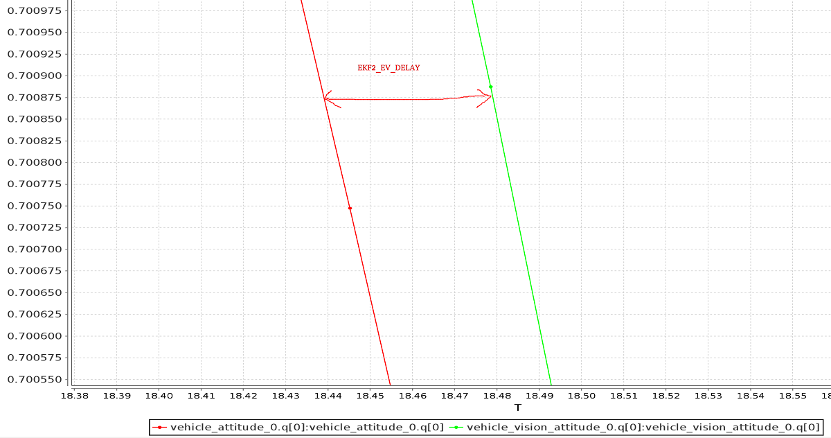
Tuning EKF2_EV_DELAY
EKF2_EV_DELAY is the Vision Position Estimator delay relative to IMU measurements. 换而言之,这是视觉系统时间戳和 IMU 时钟( EKF2 “时基” )记录的“实际”捕获时间之间的差异。
Technically this can be set to 0 if there is correct timestamping (not just arrival time) and timesync (e.g. NTP) between MoCap and (for example) ROS computers. 实际应用中,这可能需要进行一些基于经验的调整,因为通信链路中的延迟与具体设置非常相关。 It is rare that a system is set up with an entirely synchronised chain!
通过检查 IMU 速率和 EV 速率之间的偏移,可以从日志中获取对延迟的粗略估计:
INFO
A plot of external data vs. onboard estimate (as above) can be generated using FlightPlot or similar flight analysis tools.
可以通过更改参数来进一步调整该值,以找到在动态变化中最低的 EKF 更新值。
Check/Verify VIO Estimate
INFO
The MAV_ODOM_LP parameter mentioned below was removed in PX4 v1.14. This section needs to be updated.
Perform the following checks to verify that VIO is working properly before your first flight:
- Set the PX4 parameter
MAV_ODOM_LPto1. PX4 will then stream back the received external pose as MAVLink ODOMETRY messages. You can check these MAVLink messages with the QGroundControl MAVLink Inspector - Yaw the vehicle until the quaternion of the
ODOMETRYmessage is very close to a unit quaternion (w=1, x=y=z=0).- At this point, the body frame is aligned with the reference frame of the external pose system.
- 如果在不使横滚或俯仰的情况下无法使四元数接近单位四元数,则机架可能仍存在俯仰或滚动偏移。 这种情况下不要再检查机架坐标系。
- Once aligned, you can pick the vehicle up from the ground and you should see the position's z coordinate decrease. Moving the vehicle in the forward direction should increase the position's x coordinate. Moving the vehicle to the right should increase the y coordinate.
- Check that linear velocities in the message are expressed in the FRD body frame reference frame.
- Set the PX4 parameter
MAV_ODOM_LPback to 0. PX4 will stop streaming theODOMETRYmessage back.
可以通过更改参数来进一步调整该值,以找到在动态变化中最低的EKF更新值。
Put the vehicle on the ground and start streaming
ODOMETRYfeedback (as above). 油门杆推到最低并解锁。此时,设置为位置控制模式。 如果切换成功,飞控会闪绿灯。 绿灯代表:你的外部位置信息已经注入到飞控中,并且位置控制模式已经切换成功。
油门杆放到中间位置(死区),以便无人机保持飞行高度。 提高操控杆会增加参考高度,降低操控杆会降低参考高度。 Similarly, the other stick will change the position over the ground.
Increase the value of the throttle stick and the vehicle will take off. Move it back to the middle immediately afterwards.
确保无人机可以保持位置。
故障处理
First, make sure MAVROS is able to connect successfully to the flight controller.
如果连接正确, 常见问题 / 解决方案是:
Problem: I get drift / flyaways when the drone flies, but not when I carry it around with the props off.
- If using the T265 try soft-mounting it (this camera is very sensitive to high-frequency vibrations).
Problem: I get toilet-bowling when VIO is enabled.
- 确保相机的方向与启动文件中的变换匹配。 Use the QGroundControl MAVLink Inspector to verify that the velocities in the
ODOMETRYmessage coming from MAVROS are aligned to the FRD coordinate system.
- 确保相机的方向与启动文件中的变换匹配。 Use the QGroundControl MAVLink Inspector to verify that the velocities in the
Problem: I want to use vision position to do loop closing, and also want to run GPS.
- 这确实很困难,因为当他们不同意时,就会混淆 EKF。 通过测试,仅使用视觉速度更为可靠(如果您想出一种使该配置可靠的方法,请告诉我们)。
开发人员信息
Developers who are interested in extending this implementation (or writing a different one, which might not depend on ROS) should see Using Vision or Motion Capture Systems for Position Estimation.
本主题还说明了如何配置 VIO 来配合 LPE 估计器 一起使用(不推荐)。