接线指南
WARNING
PX4 does not manufacture this (or any) autopilot. Contact the manufacturer for hardware support or compliance issues.
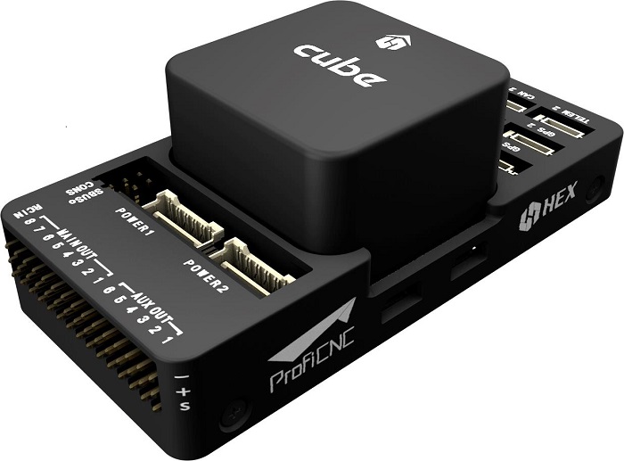
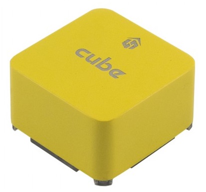
Note also that while Cube Black is fully supported by PX4, Cube Yellow and Cube Orange are Manufacturer Supported.
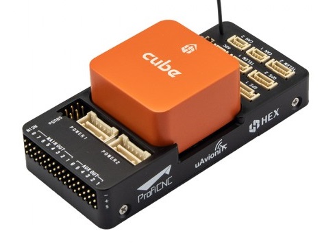
This quick start guide shows how to power the Cube® flight controllers and connect their most important peripherals.
TIP
The instructions apply to all Cube variants, including Cube Black, Cube Yellow and Cube Orange. Further/updated information may be available in the Cube User Manual (Cube Docs).
配件
Cube comes with most (or all) of the accessories you will need when purchased.
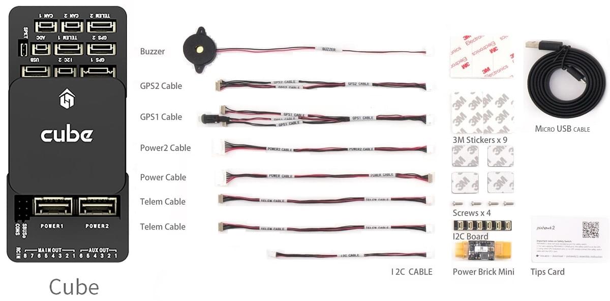
The exception is that some kits do not include a GPS, which will have to be purchased separately (see below).
接线图概览
The image below shows how to connect the most important sensors and peripherals. 我们将在下面各节中介绍它们的细节。
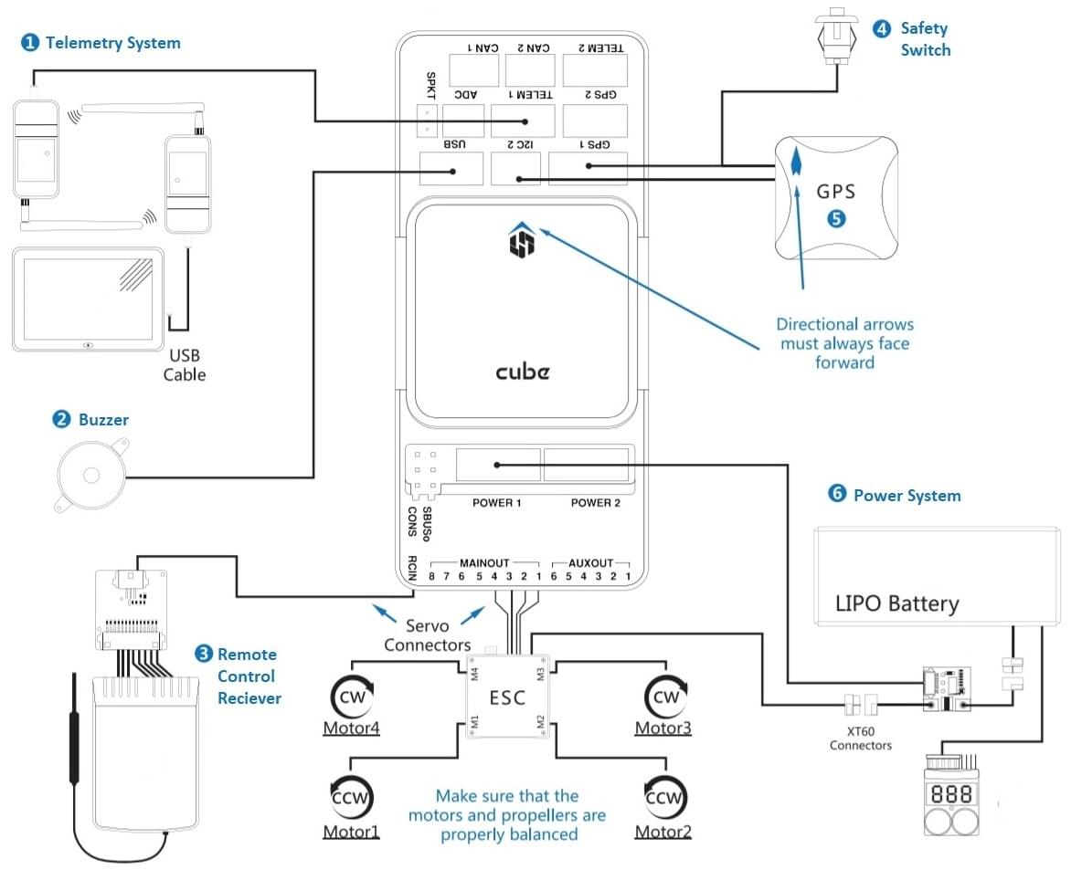
- Telemetry System — Allows you to plan/run missions, and control and monitor the vehicle in real time. 典型的包括数传、平板电脑/PC、地面站软件。
- Buzzer — Provides audio signals that indicate what the UAV is doing
- Remote Control Receiver System — Connects to a hand-held transmitter that an operator can use to manually fly the vehicle (shown is a PWM receiver with PWM->PPM converter).
- (Dedicated) Safety switch — Press and hold to lock and unlock motors. Only required if you are not using the recommended GPS with inbuilt safety switch.
- GPS, Compass, LED, Safety Switch — The recommended GPS module contains GPS, Compass, LED and Safety Switch.
- Power System — Powers Cube and the motor ESCs. 包括锂电池、电源模块和可选的电源报警系统(如果电池电量低于预定时发出警报)。
INFO
The port labeled GPS2 maps to TEL4 in PX4 (i.e. if connecting to the port labeled GPS2, assign the serial port configuration parameter for the connected hardware to TEL4).
TIP
More information about available ports can be found here: Cube > Ports.
飞控的安装和方向
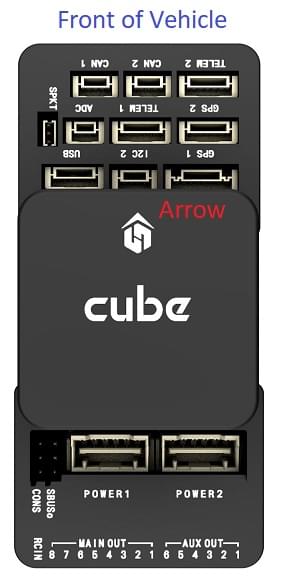
Mount the Cube as close as possible to your vehicle’s center of gravity, ideally oriented top-side up and with the arrow pointing towards the front of the vehicle (note the subtle arrow marker on top of the cube)
INFO
If the controller cannot be mounted in the recommended/default orientation (e.g. due to space constraints) you will need to configure the autopilot software with the orientation that you actually used: Flight Controller Orientation.
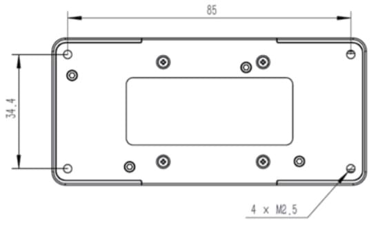
The Cube can be mounted using either vibration-damping foam pads (included in the kit) or mounting screws. The mounting screws in the Cube accessories are designed for a 1.8mm thick frameboard. Customized screws are supposed to be M2.5 with thread length inside Cube in range 6mm~7.55mm.
GPS + 罗盘 + 安全开关 + LED
The recommended GPS modules are the Here and Here+, both of which incorporate a GPS module, Compass, Safety Switch and LEDs. The difference between the modules is that Here+ supports centimeter level positioning via RTK. Otherwise they are used/connected in the same way.
WARNING
The Here+ has been superseded by the Here3 a DroneCAN RTK-GNSS that incorporate a compass and LEDs (but no safety switch). See DroneCAN for Here3 wiring and PX4 configuration information.
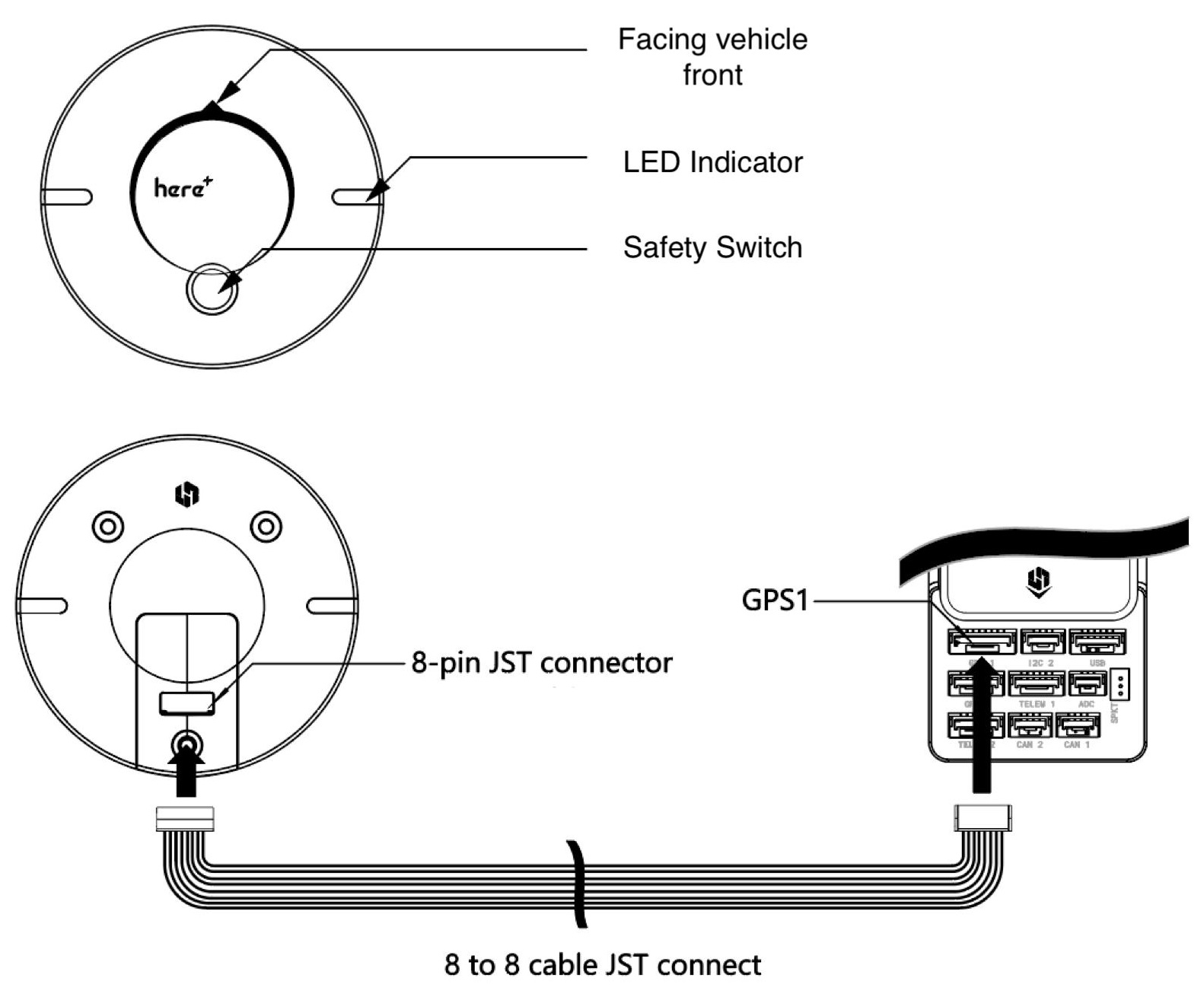
The module should be mounted on the frame as far away from other electronics as possible, with the direction marker towards the front of the vehicle (separating the compass from other electronics will reduce interference). It must be connected to the GPS1 port using the supplied 8-pin cable.
The diagram below shows a schematic view of the module and its connections.
INFO
The GPS module's integrated safety switch is enabled by default (when enabled, PX4 will not let you arm the vehicle). To disable the safety press and hold the safety switch for 1 second. You can press the safety switch again to enable safety and disarm the vehicle (this can be useful if, for whatever reason, you are unable to disarm the vehicle from your remote control or ground station).
TIP
If you want to use an old-style 6-pin GPS module, the kit comes with a cable that you can use to connect both the GPS and Safety Switch.
安全开关
The dedicated safety switch that comes with the Cube is only required if you are not using the recommended GPS (which has an inbuilt safety switch).
If you are flying without the GPS you must attach the switch directly to the GPS1 port in order to be able to arm the vehicle and fly (or via a supplied cable if using an old-style 6-pin GPS).
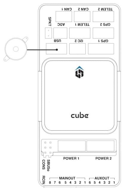
蜂鸣器
The buzzer plays tones and tunes that provide audible notification of vehicle status (including tones that are helpful for debugging startup issues, and that notify of conditions that might affect safe operation of the vehicle).
The buzzer should be connected to the USB port as shown (no further configuration is required).
遥控器
A remote control (RC) radio system is required if you want to manually control your vehicle (PX4 does not require a radio system for autonomous flight modes).
You will need to select a compatible transmitter/receiver and then bind them so that they communicate (read the instructions that come with your specific transmitter/receiver).
The instructions below show how to connect the different types of receivers.
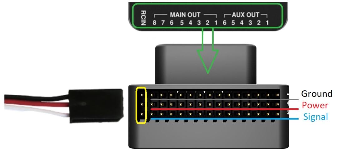
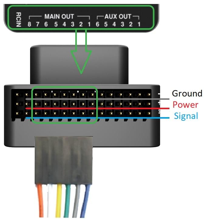
PPM-SUM / Futaba S.Bus 接收机
Connect the ground(-),power(+),and signal(S) wires to the RC pins using the provided 3-wire servo cable.
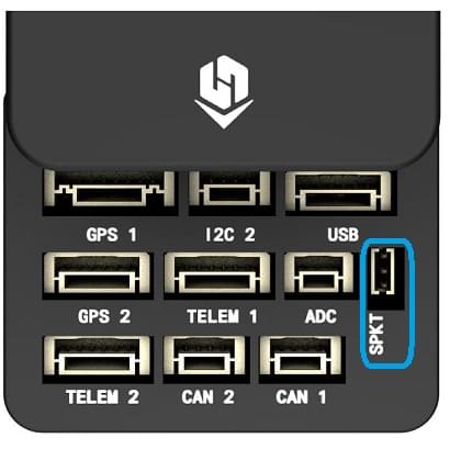
Spektrum 卫星接收器
Spektrum DSM, DSM2, and DSM-X Satellite RC receivers connect to the SPKT/DSM port.
PWM 接收机
The Cube cannot directly connect to PPM or PWM receivers that have an individual wire for each channel. PWM receivers must therefore connect to the RCIN port via a PPM encoder module, which may be purchased from hex.aero or proficnc.com.
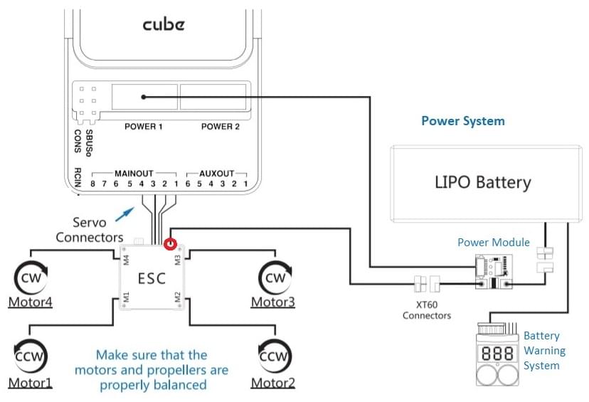
电源
Cube is typically powered from a Lithium Ion Polymer (LiPo) Battery via a Power Module (supplied with the kit) that is connected to the POWER1 port. The power module provides reliable supply and voltage/current indication to the board, and may separately supply power to ESCs that are used to drive motors on a multicopter vehicle.
A typical power setup for a Multicopter vehicle is shown below.
INFO
The power (+) rail of MAIN/AUX is not powered by the power module supply to the flight controller. In order to drive servos for rudders, elevons, etc., it will need to be separately powered.
This can be done by connecting the power rail to a BEC equipped ESC, a standalone 5V BEC, or a 2S LiPo battery. Ensure the voltage of servo you are going to use is appropriate!
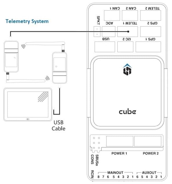
数传系统(可选)
A telemetry system allows you to communicate with, monitor, and control a vehicle in flight from a ground station (for example, you can direct the UAV to a particular position, or upload a new mission).
The communication channel is via Telemetry Radios. The vehicle-based radio should be connected to the TELEM1 port (if connected to this port, no further configuration is required). The other radio is connected to your ground station computer or mobile device (usually via USB).
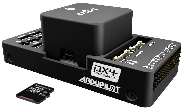
SD 卡
SD cards are highly recommended as they are needed to log and analyse flight details, to run missions, and to use UAVCAN-bus hardware. Insert the Micro-SD card into Cube as shown (if not already present).
TIP
For more information see Basic Concepts > SD Cards (Removable Memory).
电机
Motors/servos are connected to the MAIN and AUX ports in the order specified for your vehicle in the Airframe Reference.
INFO
This reference lists the output port to motor/servo mapping for all supported air and ground frames (if your frame is not listed in the reference then use a "generic" airframe of the correct type).
WARNING
The mapping is not consistent across frames (e.g. you can't rely on the throttle being on the same output for all plane frames). Make sure to use the correct mapping for your vehicle.
其它外设
The wiring and configuration of optional/less common components is covered within the topics for individual peripherals.
INFO
If connecting peripherals to the port labeled GPS2, assign the PX4 serial port configuration parameter for the hardware to TEL4 (not GPS2).
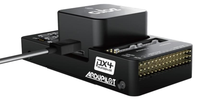
配置
Configuration is performed using QGroundContro.
After downloading, installing and running QGroundControl, connect the board to your computer as shown.
Basic/common configuration information is covered in: Autopilot Configuration.
QuadPlane specific configuration is covered here: QuadPlane VTOL Configuration
Bootloader Updates
If you get the [Program PX4IO(../getting_started/tunes.md#program-px4io) warning tone after flashing PX4 firmware, you may need to update the bootloader.
The safety switch can be used to force bootloader updates. To use this feature de-power the Cube, hold down the safety switch, then power the Cube over USB.
更多信息
- Cube Black
- Cube Yellow
- Cube Orange
- Cube Docs (Manufacturer):