Holybro X500 + Pixhawk4 Build
INFO
Holybro initially supplied this kit with a Holybro Pixhawk 4), but at time of writing this has been upgraded to a Holybro Pixhawk 6C. 这个构建记录仍然具有相关性,因为套装组件几乎是一样的,而且随着飞行控制器升级,很可能仍然如此。
This topic provides full instructions for building the kit and configuring PX4 using QGroundControl.
Key information
- Full Kit: Holybro X500 Kit
- 飞行控制器: Pixhawk 4
- Assembly time (approx.): 3.75 hours (180 minutes for frame, 45 minutes for autopilot installation/configuration)
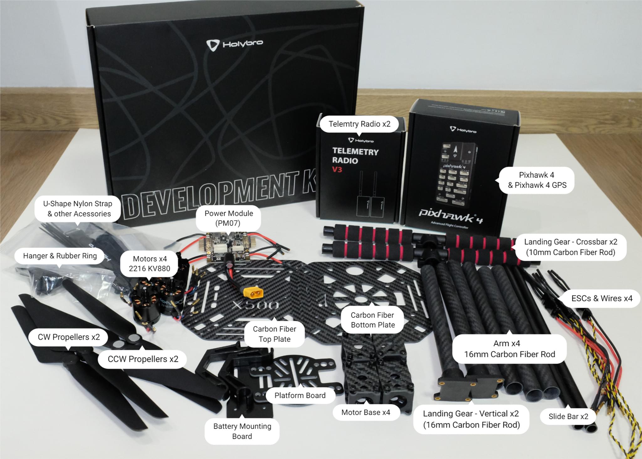
Bill of materials
The Holybro X500 Kit includes almost all the required components:
- Pixhawk 4 autopilot
- Holybro M8N GPS
- Power Management - PM07
- Holybro Motors - 2216 KV880 x4 (superseded - check spare parts list for current version).
- Holybro BLHeli S ESC 20A x4 (superseded - check spare parts list for current version).
- Propellers - 1045 x4 (superseded - check spare parts list for current version).
- Battery Strap
- 电源线和信号线
- Wheelbase - 500 mm
- Dimensions - 410x410x300 mm
- 433 MHz / 915 MHz Holybro数传电台
Additionally you will need a battery and receiver (compatible radio system) if you want to control the drone manually.
硬件
This section lists all hardware for the frame and the autopilot installation.
| Item | 描述 | Quantity |
|---|---|---|
| Bottom plate | Carbon fiber (2mm thick) | 1 |
| Top plate | Carbon fiber (1.5mm thick) | 1 |
| Arm | Carbon fiber tube (Diameter: 16mm length: 200mm) | 4 |
| Landing gear - Vertical pole | Carbon fiber tube + engineering plastic | 2 |
| Landing gear - Cross bar | Carbon fiber tube + engineering plastic + foam | 2 |
| Motor base | Consists of 6 parts and 4 screws 4 nuts | 4 |
| Slide bar | Diameter: 10mm length: 250mm | 2 |
| Battery mounting board | Thickness: 2mm | 1 |
| Battery pad | 3mm Silicone sheet black | 1 |
| Platform board | Thickness: 2mm | 1 |
| Hanger & rubber ring gasket | Inner hole diameter: 10mm black | 8 |
Electronics
| 物品描述 | Quantity |
|---|---|
| Pixhawk4 & Assorted Cables | 1 |
| Pixhawk4 GPS Module | 1 |
| Power Management PM07 (with pre-soldered ESC power cables) | 1 |
| Motors 2216 KV880(V2 Update) | 4 |
| Holybro BLHeli S ESC 20A x4 | 1 |
| 433 MHz / 915 MHz Holybro数传电台 | 1 |
Tools needed
The following tools are used in this assembly:
- 1.5 mm Hex screwdriver
- 2.0 mm Hex screwdriver
- 2.5 mm Hex screwdriver
- 3mm Phillips screwdriver
- 5.5 mm socket wrench or small piler
- Wire cutters
- Precision tweezers
组装
Estimate time to assemble is 3.75 hours (180 minutes for frame, 45 minutes for autopilot installation/configuration)
Start by assembling the landing gear. Unscrew the landing gear screws and insert the vertical pole (figures 1 and 2).
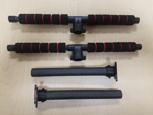
Figure 2: Landing gear components
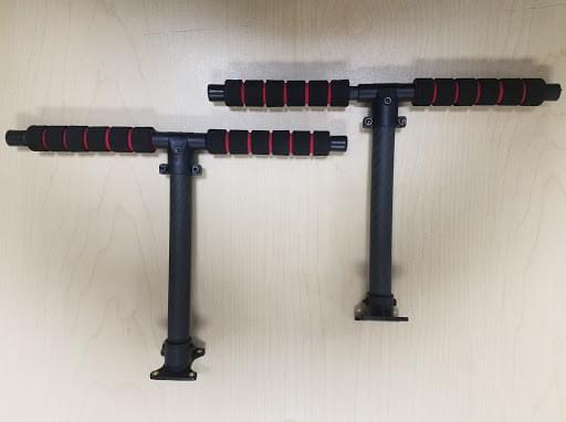
Figure 2: Landing gear assembled
Then put the 4 arms through the 4 motor bases shown in figure 3. Make sure the rods protrude the base slightly and are consistent throughout all 4 arms, and be sure to have the motor wires facing outward.
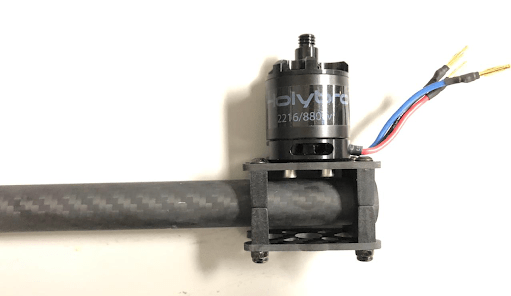
Figure 3: Attach arms to motor bases
Insert 4 nylon screws and nylon standoffs and attach the power module PM07 to the bottom plate using 4 nylon nuts as shown in Figures 4.
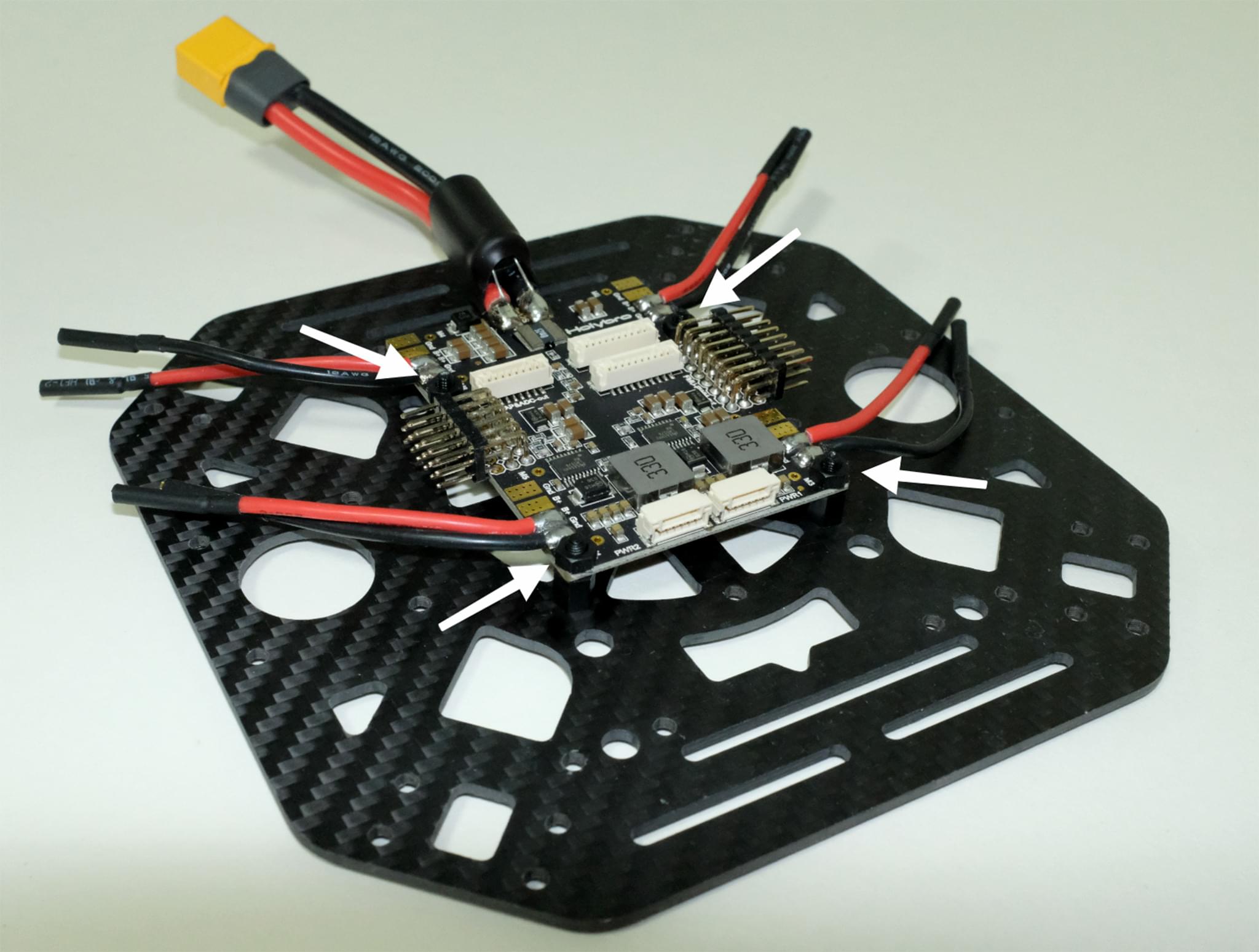
Figure 4: Attach power module
Feed the 4 motor ESCs through each of the arms and connect the 3-wires end to the motors shown in Figure 5.

Figure 5: Connect motors
Connect the ESCs power wires onto the power module PM07, black->black and red->red, ESC PWM signal wires goes to "FMU-PWM-Out". Make sure you connect the motor ESC PWM wires in the correct order. Refer to Figure 7 for airframe motor number and connect to the corresponding number on the PM07 board.
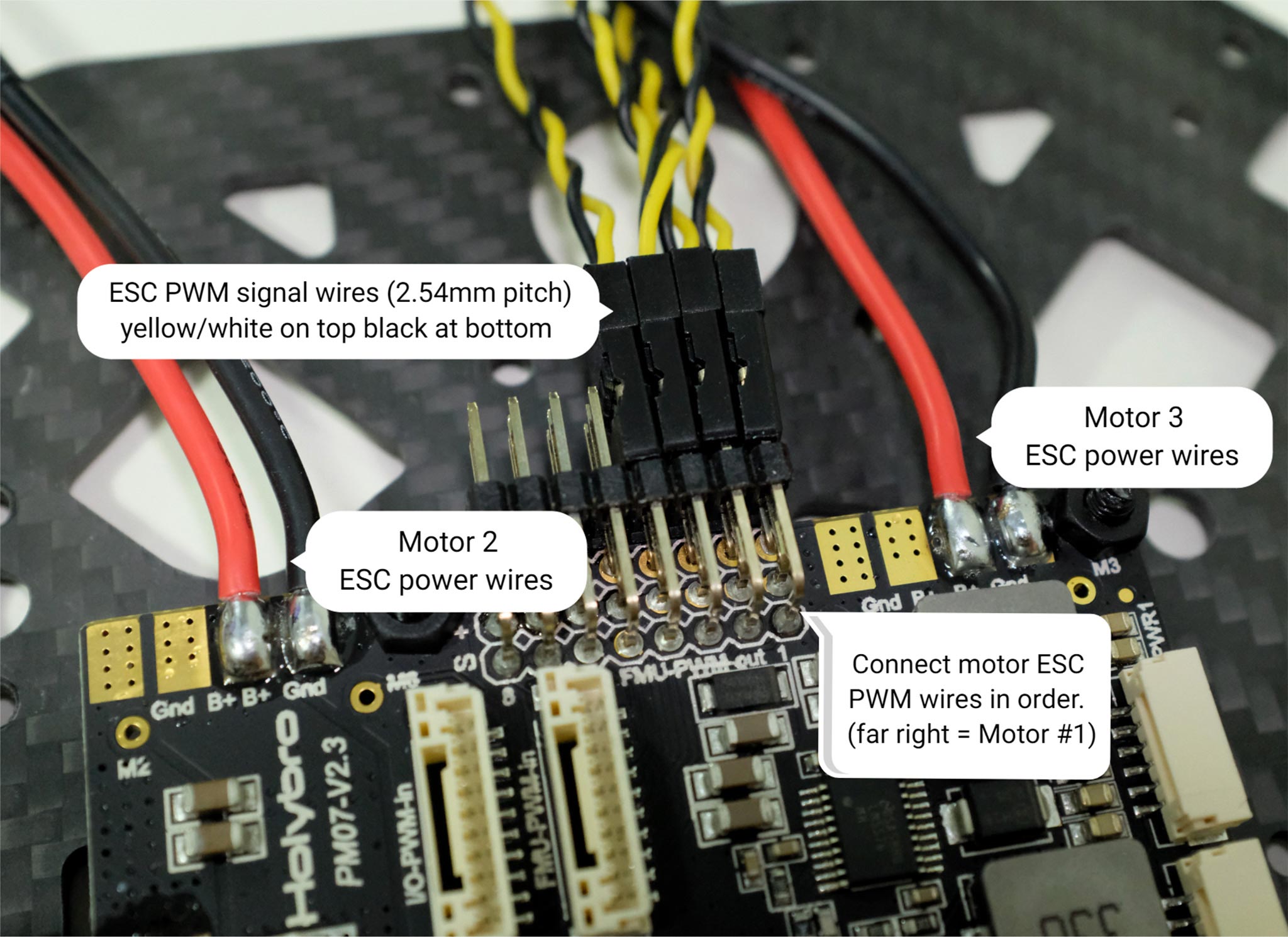 Figure 7: ESC power module and signal wiring
The color on top of the motor indicate the spin direction (figure 7-1), black tip is clockwise, and white tip is counter-clockwise. Make sure the follow the PX4 quadrotor x airframe reference for motor direction (figure 7-2).
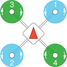
Figure 7: Motor order/direction diagram
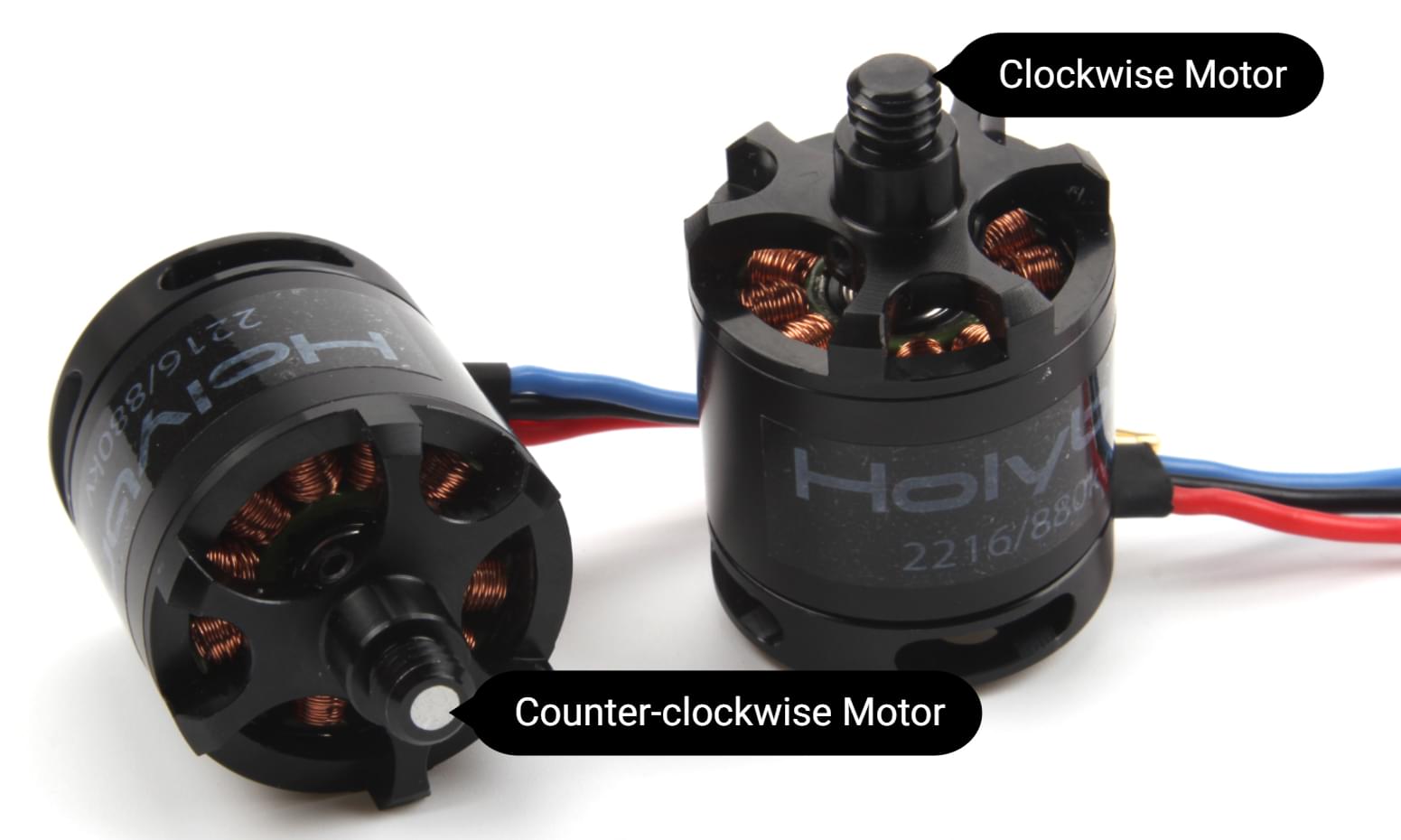
Figure 7-1: Motor direction
Connect the 10 pin cables to FMU-PWM-in, the 6 pin cables to the PWR1 on the PM07 power module.
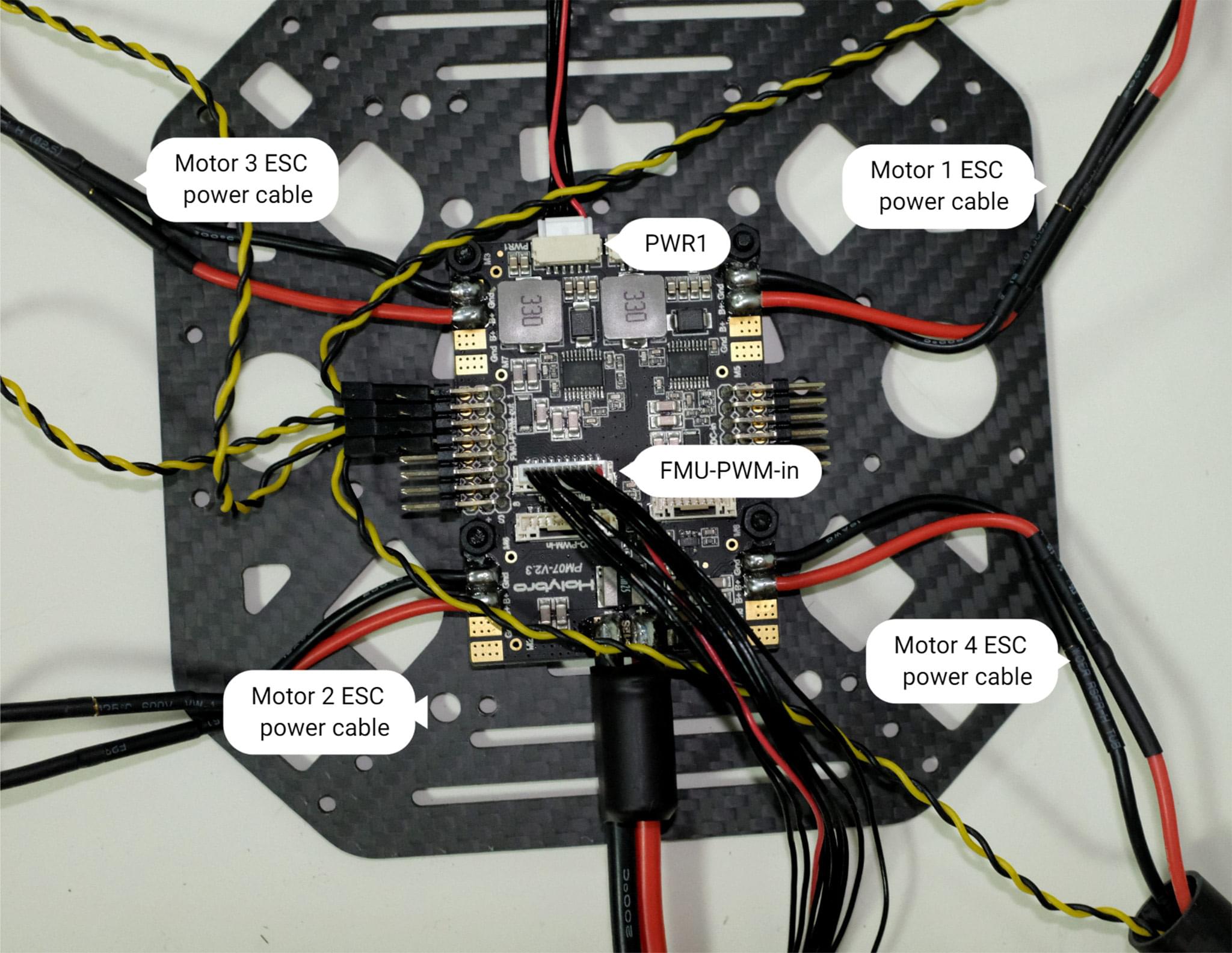
Figure 8: Power module PWM and power wiring
If you want to mount the GPS on the top plate, you can now secure the GPS mount onto the top plate using 4 screws and nuts.

Figure 9: Secure GPS mount onto top plate
Feed the PM07 cables through the top plate. Connect the top and bottom plate by using 4 U-shaped nylon straps, screws, and nuts on each side, ensure that the motor ESC cables are inside the U-shape nylon straps like Figure 10, keep the nut loose.
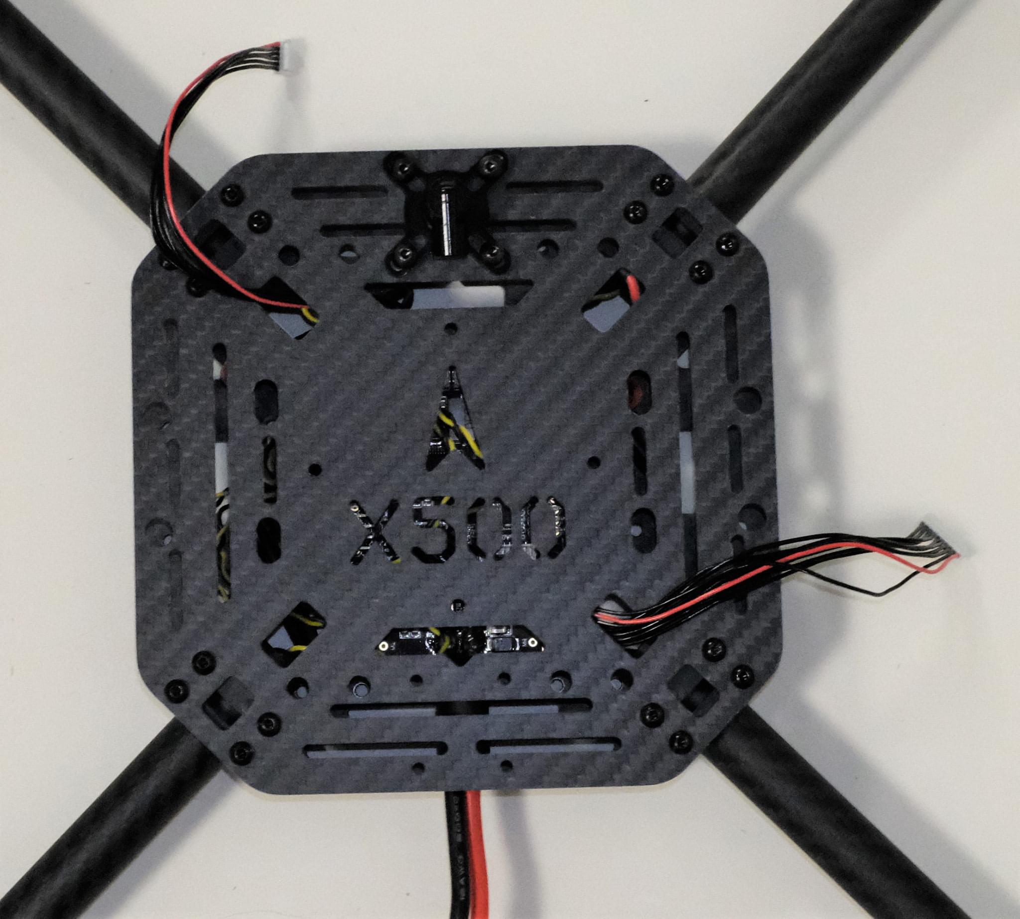
Figure 10-1: Feed power module cables through top plate

Figure 10-2: Connecting top and bottom plate
Push the arm tubes a bit into the frame and make sure the amount of protrusion (red square from Figure 11) are consistent on all 4 arms. Ensure all the motors are pointed directly upward, then tighten all the nuts and screws.
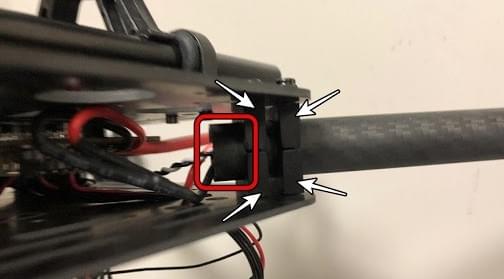
Put the hanger gaskets into the 4 hangers and mount them onto the bottom plate using 8 hex screws (Figure 11). The screw holes are noted by the white arrow in Figure 12. We recommend tilting the drone sideway to make the installation easier.

Figure 11: Hanger gaskets
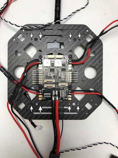
Figure 12: Screw holes
Insert the slide bars onto the hanger rings (Figure 13). Assemble the battery mount and platform board and mount them onto the slide bars as shown in Figure 14.
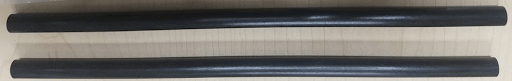
Figure 13: Slide bars

Figure 14: Battery mount on slide bars
Mount the landing gear onto the bottom plate. We recommend tilting the drone sideway to make this installation process easier.
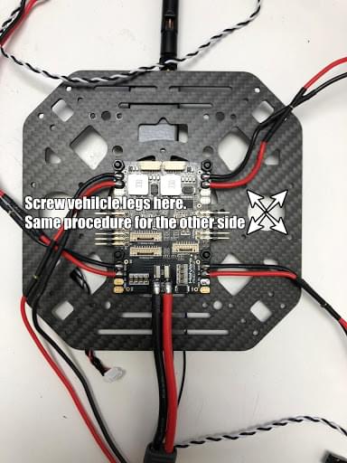
Figure 15: Landing Gear
Use the tape and stick the GPS to the top of the GPS mast and mount the GPS mast. Make sure the arrow on the gps is pointing forward (Figure 16).

Figure 16: GPS and mast
Mount the telemetry radio onto the top plate. Plug the telemetry cable into
TELEM1port and GPS module toGPS MODULEport on the flight controller. Plug the cable from PM07FMU-PWM-intoI/O-PWM-outon the FC and PM07PWR1toPOWER1on the FC, as shown in Figure 17.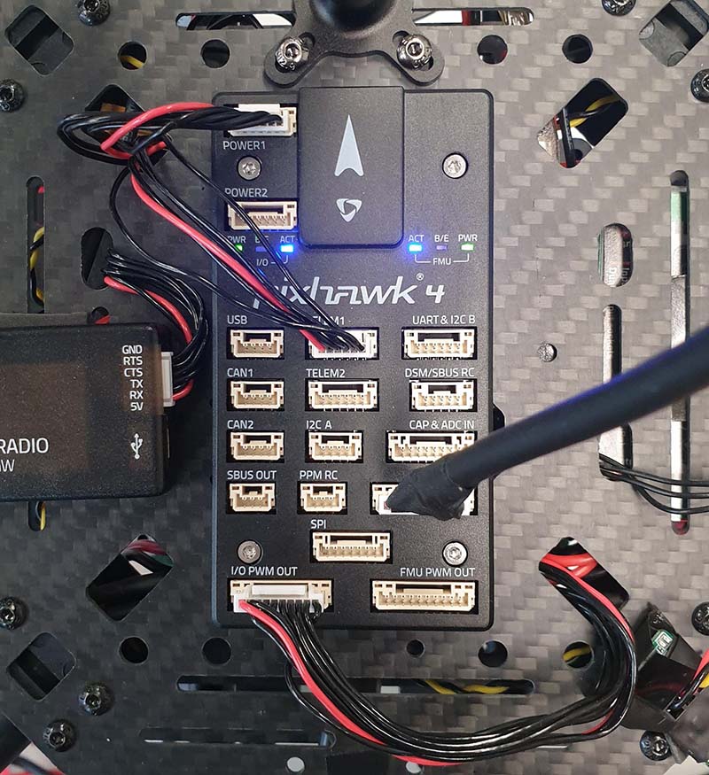
Figure 17: Mount telemetry radio/plug in PWM and Power cables to Flight controller.
Please refer to Pixhawk 4 Quick Start for more information.
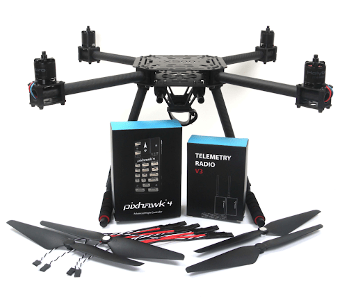
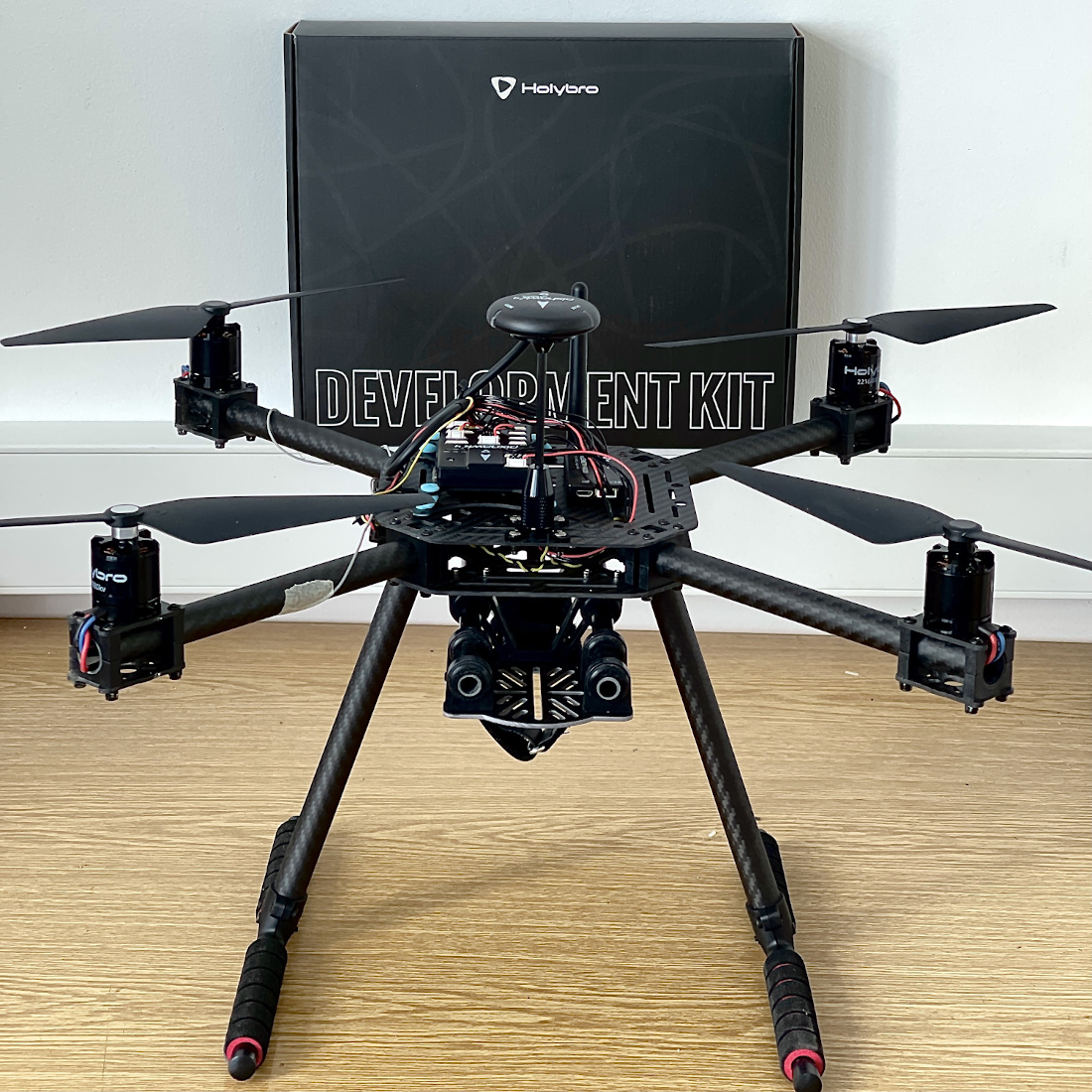
That's it. The fully assembled kit is shown below:
PX4 配置
TIP
Full instructions for installing and configuring PX4 can be found in Basic Configuration.
QGroundControl is used to install the PX4 autopilot and configure/tune it for the X500 frame. Download and install QGroundControl for your platform.
First update the firmware, airframe, and actuator mappings:
您需要选择 Holybro S500 机架(Quadrotor x > Holybro S500)。
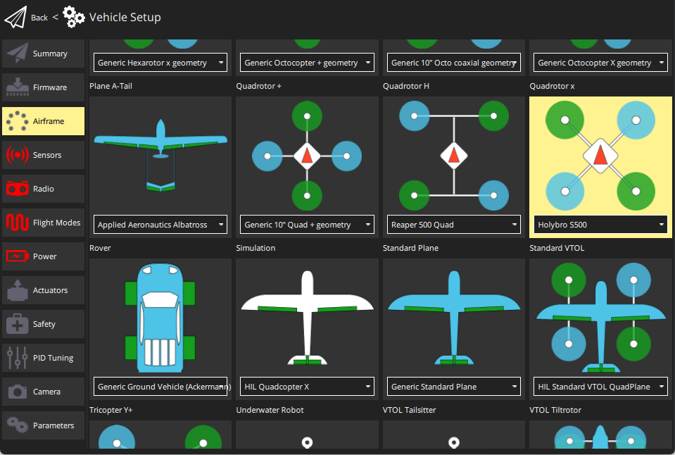
- You should not need to update the vehicle geometry (as this is a preconfigured airframe).
- Assign actuator functions to outputs to match your wiring.
- Test the configuration using the sliders.
Then perform the mandatory setup/calibration:
Ideally you should also do:
调试
Airframe selection sets default autopilot parameters for the frame. 这些足以让它起飞,但是为你的特定框架调整专有参数是一个好主意。
For instructions on how, start from Autotune.
Acknowledgements
This build log was provided by the Dronecode Test Flight Team.