Holybro X500 + Pixhawk4 Build
INFO
Holybro initially supplied this kit with a Holybro Pixhawk 4), but at time of writing this has been upgraded to a Holybro Pixhawk 6C. Цей журнал збірки все ще актуальний, оскільки збірка комплекту практично однакова і, ймовірно, залишиться такою ж, оскільки контролер польоту оновлюється.
This topic provides full instructions for building the kit and configuring PX4 using QGroundControl.
Основна Інформація
- Full Kit: Holybro X500 Kit
- Flight controller: Pixhawk 4
- Assembly time (approx.): 3.75 hours (180 minutes for frame, 45 minutes for autopilot installation/configuration)
Специфікація матеріалів
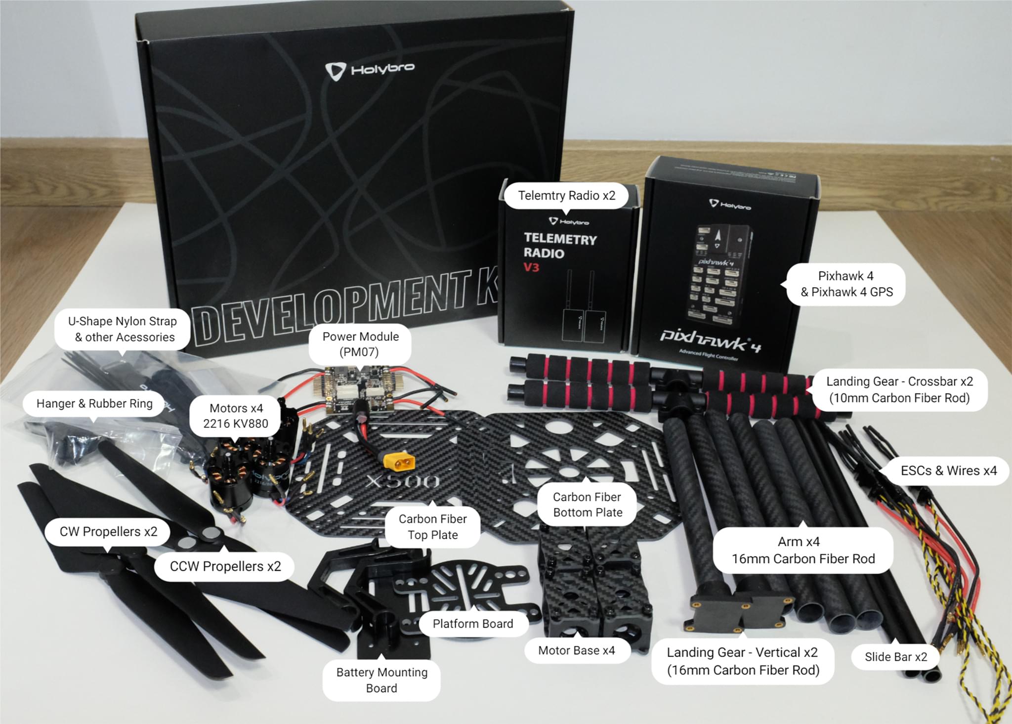
The Holybro X500 Kit includes almost all the required components:
- Pixhawk 4 autopilot
- Holybro M8N GPS
- Power Management - PM07
- Holybro Motors - 2216 KV880 x4 (superseded - check spare parts list for current version).
- Holybro BLHeli S ESC 20A x4 (superseded - check spare parts list for current version).
- Propellers - 1045 x4 (superseded - check spare parts list for current version).
- Ремінь для акумулятора
- Живлення та радіокабелі
- Колісна база - 500 мм
- Розміри - 410x410x300 мм
- 433 MHz / 915 MHz Holybro Telemetry Radio
Additionally you will need a battery and receiver (compatible radio system) if you want to control the drone manually.
Головне апаратне забезпечення
У цьому розділі перераховано все обладнання для встановлення рами та автопілота.
| Елемент | Опис | Кількість |
|---|---|---|
| Нижня пластина | Вуглецеве волокно (товщиною 2 мм) | 1 |
| Верхня пластина | Вуглецеве волокно (товщиною 1.5мм) | 1 |
| Кронштейн | Вуглепластикова трубка (діаметр: 16 мм, довжина: 200 мм) | 4 |
| Шасі - Вертикальна стійка | Вуглепластикова трубка + інженерний пластик | 2 |
| Шасі - Поперечна балка | Вуглепластикова трубка + інженерний пластик + пінопласт | 2 |
| Моторна база | Складається з 6 частин і 4 гвинтів 4 гайок | 4 |
| Бокова панель | Діаметр: 10мм довжина: 250мм | 2 |
| Плата кріплення акумулятора | Товщина: 2мм | 1 |
| Підставка для батареї | Чорний лист силікону товщиною 3 мм | 1 |
| Плата платформи | Товщина: 2мм | 1 |
| Hanger & rubber ring gasket | Діаметр внутрішнього отвору: 10 мм чорний | 8 |
Електроніка
| Опис предмету | Кількість |
|---|---|
| Pixhawk4 & Assorted Cables | 1 |
| Pixhawk4 GPS Module | 1 |
| Управління живленням PM07 (з попередньо припаяними кабелями живлення ESC) | 1 |
| Двигуни 2216 KV880 (оновлення V2) | 4 |
| Holybro BLHeli S ESC 20A x4 | 1 |
| 433 MHz / 915 MHz Holybro Telemetry Radio | 1 |
Необхідні інструменти
У цій збірці використовуються наступні інструменти:
- Викрутка з шестигранником 1,5 мм
- Викрутка з шестигранником 2,0 мм
- Викрутка з шестигранником 2,5 мм
- Шуруповерт Phillips 3 мм
- Торцевий ключ 5,5 мм або невелика викрутка
- Кусачки
- Прецизійний пінцет
Збірка
Час збірки (приблизно): 3.75 години (180 хвилин на раму, 45 хвилин на встановлення/налаштування автопілота)
- Почніть зі збирання шасі. Відкрутіть гвинти шасі і вставте вертикальну стійку (зобр. 1 і 2).
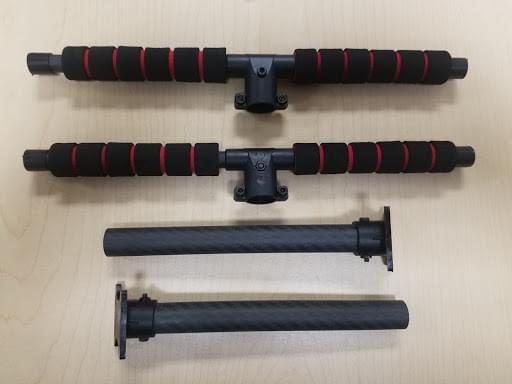
Figure 2: Landing gear components
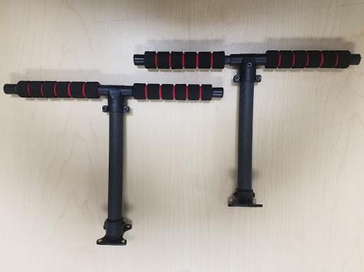
Figure 2: Landing gear assembled
- Потім просуньте 4 кронштейни через 4 основи двигуна, як показано на малюнку 3. Переконайтеся, що штанги злегка виступають з основи і є однаковими на всіх 4-х плечах, а також переконайтеся, що дроти електродвигуна спрямовані назовні.
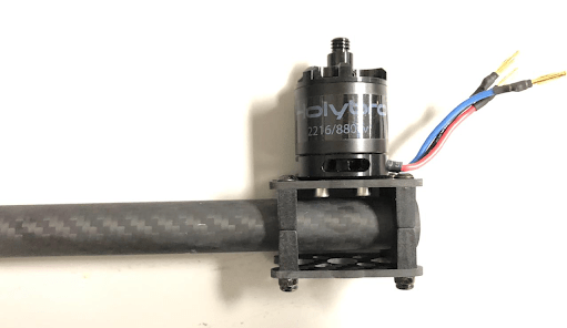
Figure 3: Attach arms to motor bases
- Вставте 4 нейлонові гвинти та нейлонові стійки і прикріпіть модуль живлення PM07 до нижньої панелі за допомогою 4 нейлонових гайок, як показано на зображенні 4.
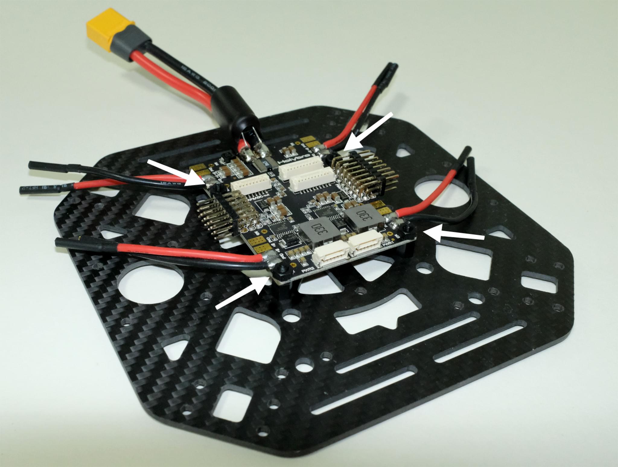
Figure 4: Attach power module
- Протягніть 4 двигуни ESC через кожне з кронштейнів і підключіть трижильні дроти до двигунів, як показано на зображенні 5.

Figure 5: Connect motors
- Connect the ESCs power wires onto the power module PM07, black->black and red->red, ESC PWM signal wires goes to "FMU-PWM-Out". Переконайтеся, що ви підключили дроти ШІМ ESC двигуна в правильному порядку. Номер двигуна повітряного корпусу дивіться на зображенні 7 і підключіть його до відповідного номера на платі PM07.
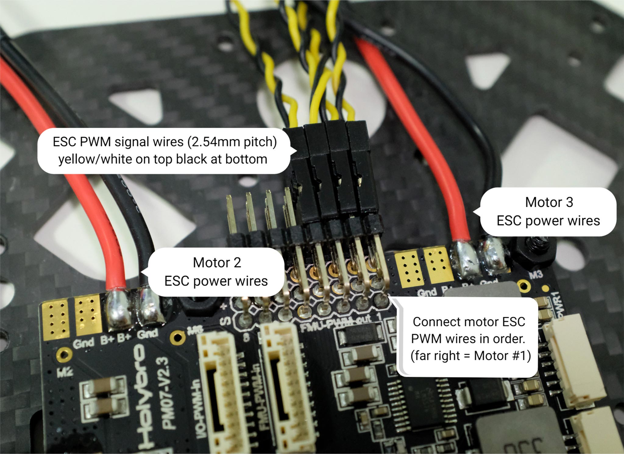 Figure 7: ESC power module and signal wiring
Колір на верхній частині двигуна вказує на напрямок обертання (зображення 7-1), чорний кінчик - за годинниковою стрілкою, а білий - проти годинникової стрілки. Переконайтеся, що при виборі напрямку двигуна ви дотримуєтесь орієнтира px4 quadrotor x airframe (зображення 7-2).
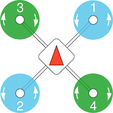
Figure 7: Motor order/direction diagram
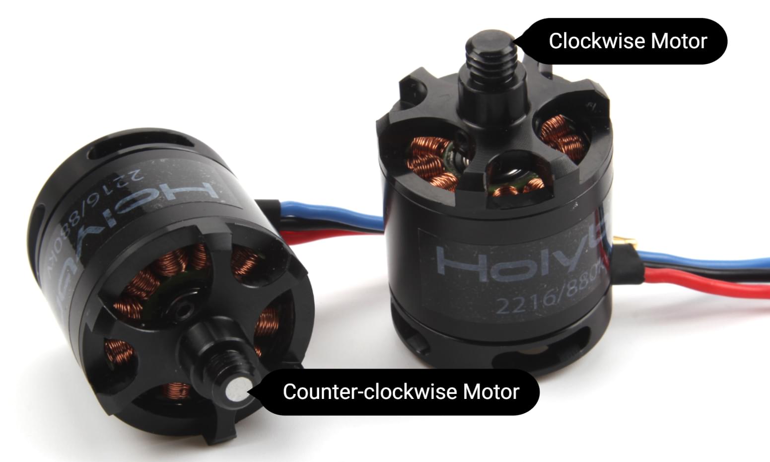
Figure 7-1: Motor direction
- Підключіть 10-контактні кабелі до FMU-PWM-in, а 6-контактні - до PWR1 на модулі живлення PM07.
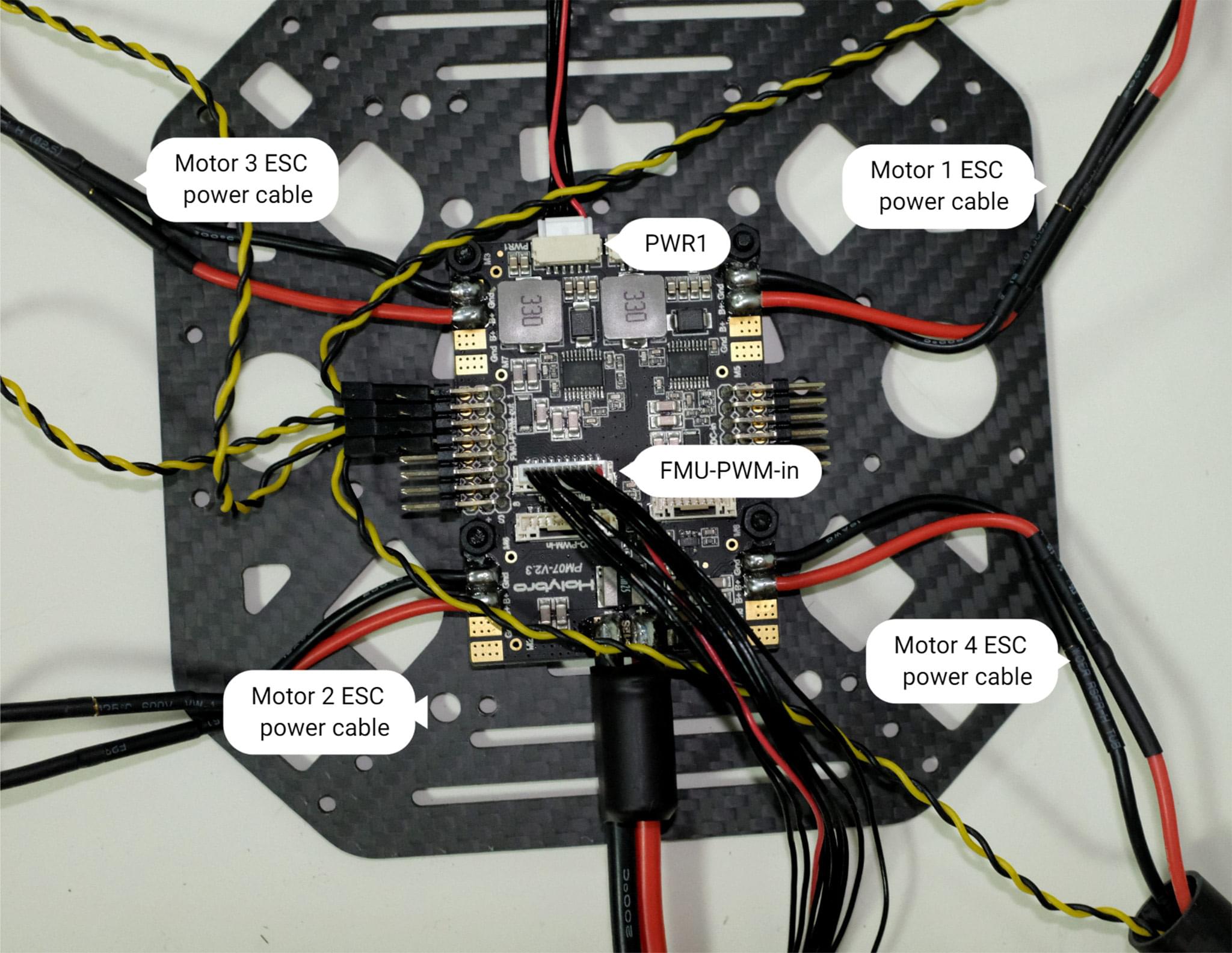
Figure 8: Power module PWM and power wiring
- Якщо ви хочете встановити GPS на верхній панелі, то тепер ви можете закріпити кріплення GPS на верхній панелі за допомогою 4 гвинтів і гайок.

Figure 9: Secure GPS mount onto top plate
- Протягніть кабелі PM07 через верхню пластину. З'єднайте верхню і нижню пластини за допомогою 4 U-подібних нейлонових ременів, гвинтів і гайок з кожного боку, переконайтеся, що кабелі ESC двигуна знаходяться всередині U-подібних нейлонових ременів, як показано на зображенні 10, гайки не затягуйте.
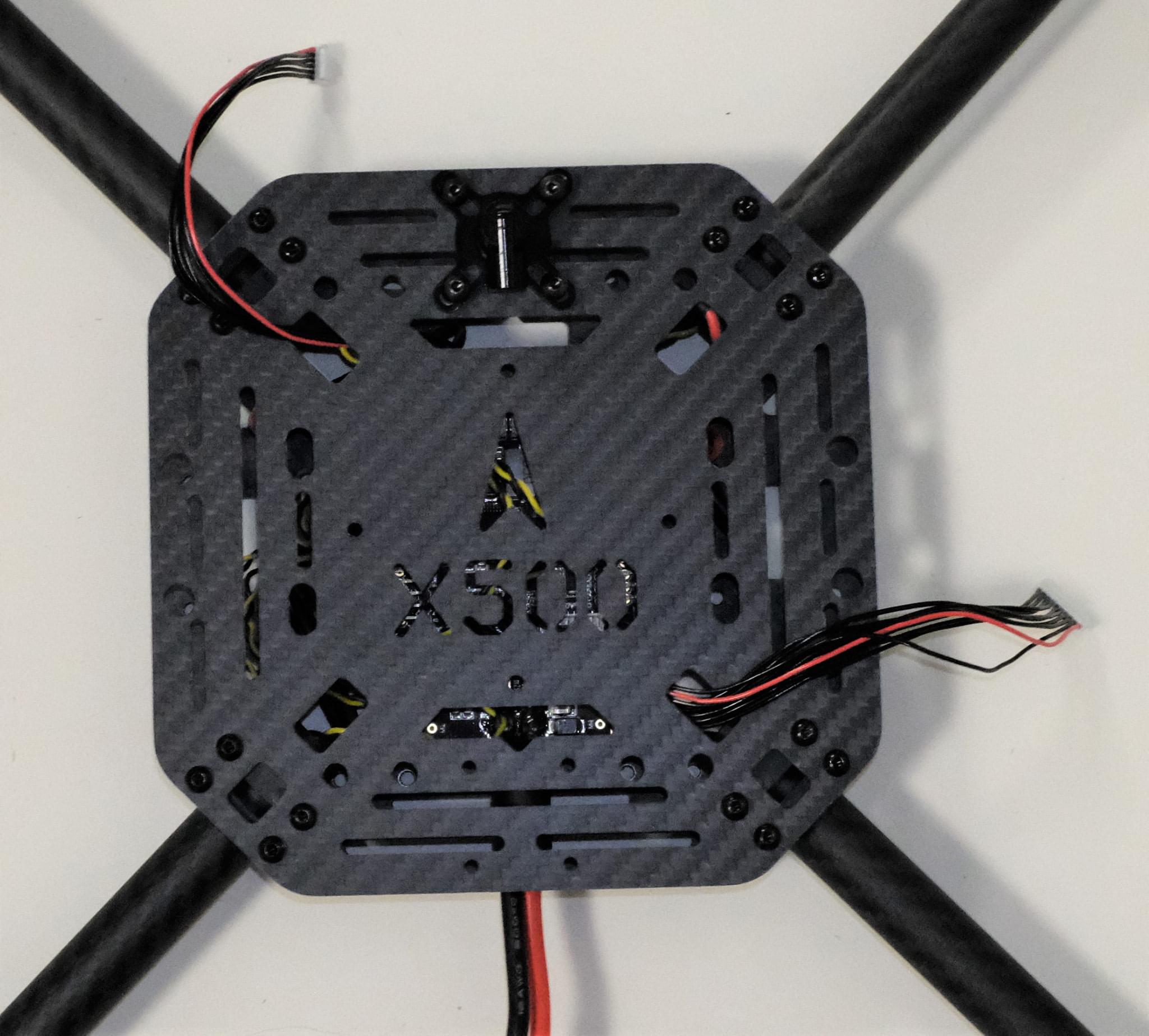
Figure 10-1: Feed power module cables through top plate

Figure 10-2: Connecting top and bottom plate
- Трохи всуньте трубки кронштейнів у раму і переконайтеся, що величина виступу (червоний квадрат на зображенні 11) є однаковою на всіх 4-х кронштейнах. Переконайтеся, що всі двигуни спрямовані прямо вгору, а потім затягніть усі гайки та гвинти.
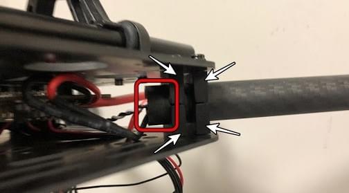
- Вставте прокладки для підвісів у 4 підвіси та закріпіть їх на нижній пластині за допомогою 8 шестигранних гвинтів (Зображення 11). Отвори для гвинтів позначені білою стрілкою на зображенні 12. Ми рекомендуємо нахилити дрон убік, щоб полегшити встановлення.

Figure 11: Hanger gaskets
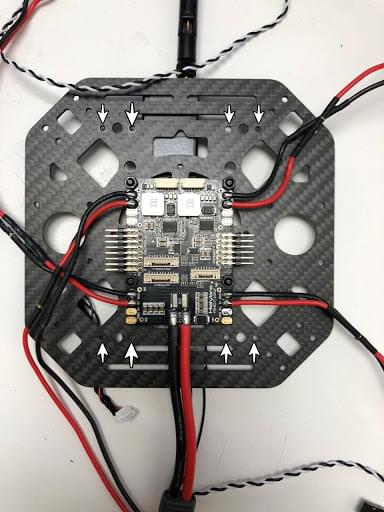
Figure 12: Screw holes
- Вставте направляючі планки на кільця кріплення (зображення 13). Зберіть кріплення для батареї та плату платформи і встановіть їх на направляючі, як показано на зображенні 14.
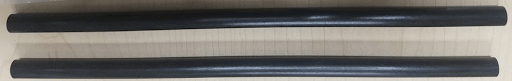
Figure 13: Slide bars

Figure 14: Battery mount on slide bars
- Встановіть шасі на нижню пластину. Ми рекомендуємо нахилити дрон убік, щоб полегшити встановлення.
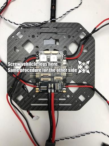
Figure 15: Landing Gear
- За допомогою скотча приклейте GPS до верхньої частини GPS-щогли і встановіть її на щоглу. Переконайтеся, що стрілка на gps вказує вперед (зображення 16).

Figure 16: GPS and mast
- Встановіть телеметричну радіостанцію на верхню пластину. Plug the telemetry cable into
TELEM1port and GPS module toGPS MODULEport on the flight controller. Plug the cable from PM07FMU-PWM-intoI/O-PWM-outon the FC and PM07PWR1toPOWER1on the FC, as shown in Figure 17.
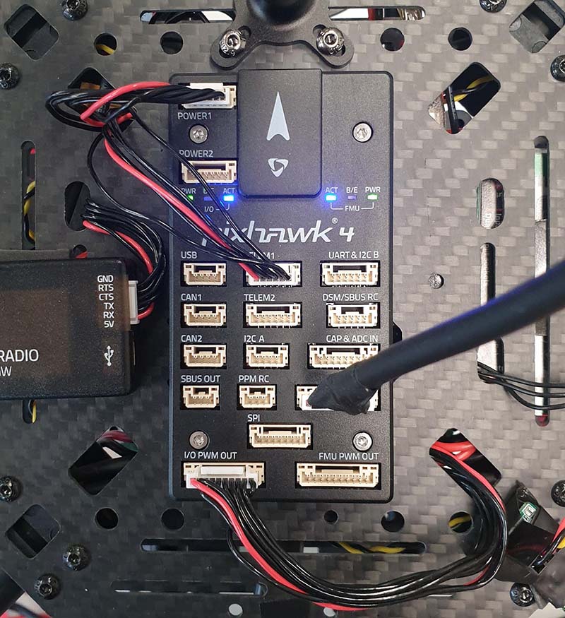
Figure 17: Mount telemetry radio/plug in PWM and Power cables to Flight controller.
Please refer to Pixhawk 4 Quick Start for more information.
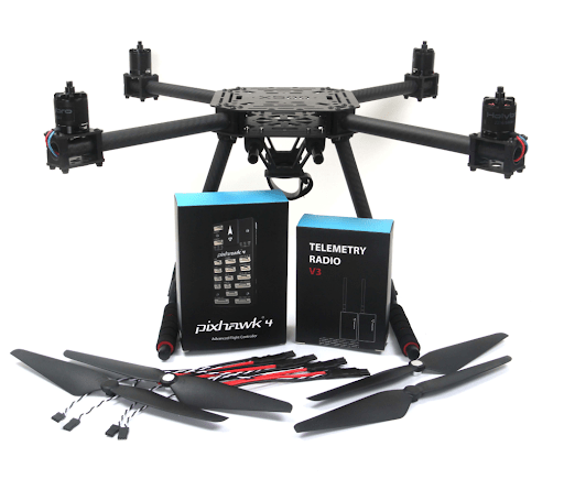
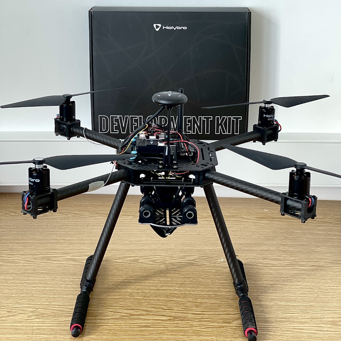
Ось і все. Повністю зібраний комплект показаний нижче:
Конфігурація PX4
TIP
Full instructions for installing and configuring PX4 can be found in Basic Configuration.
QGroundControl is used to install the PX4 autopilot and configure/tune it for the X500 frame. Download and install QGroundControl for your platform.
Спочатку оновіть прошивку, конструкцію та відображення актуаторів:
You will need to select the Holybro S500 airframe (Quadrotor x > Holybro S500).
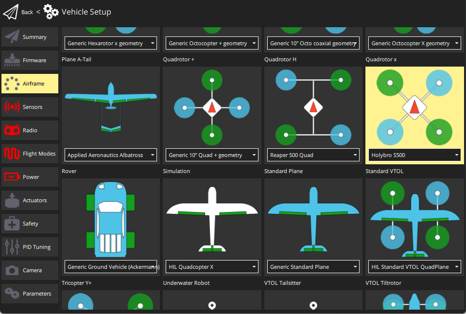
- Вам не потрібно оновлювати геометрію транспортного засобу (оскільки це попередньо налаштована конструкція повітряного каркасу).
- Призначте функції приводу до актуаторів, щоб відповідати вашому підключенню.
- Перевірте конфігурацію, використовуючи слайдери.
Потім виконайте обов'язкове налаштування / калібрування:
В ідеалі ви також повинні зробити:
Вдосконалення
Airframe selection sets default autopilot parameters for the frame. Ці вистачають для польоту, але це добра ідея налаштувати параметри для конкретної конструкції рами.
For instructions on how, start from Autotune.
Подяки
Цей журнал збірки був наданий Командою тестового польоту Dronecode.