Gimbal Configuration
This page explains how to configure and control a gimbal that has an attached camera (or any other payload).
개요
PX4 contains a generic mount/gimbal control driver that supports different input and output methods:
- The input method defines the protocol used to command a gimbal mount that is managed by PX4. This might be an RC controller, a MAVLink command sent by a GCS, or both — automatically switching between them.
- The output method defines how PX4 communicates with the connected gimbal. The recommended protocol is MAVLink v2, but you can also connect directly to a flight controller PWM output port.
PX4 takes the input signal and routes/translates it to be sent through to the output. Any input method can be selected to drive any output.
Both the input and output are configured using parameters. The input is set using the parameter MNT_MODE_IN. By default this is set to Disabled (-1) and the driver does not run. After selecting the input mode, reboot the vehicle to start the mount driver.
You should set MNT_MODE_IN to one of: RC (1), MAVlink gimbal protocol v2 (4) or Auto (0) (the other options are deprecated). If you select Auto (0), the gimbal will automatically select either RC or MAVLink input based on the latest input. Note that the auto-switch from MAVLink to RC requires a large stick motion!
The output is set using the MNT_MODE_OUT parameter. By default the output is set to a PXM port (AUX (0)). If the MAVLink Gimbal Protocol v2 is supported by your gimbal, you should instead select MAVLink gimbal protocol v2 (2).
The full list of parameters for setting up the mount driver can be found in Parameter Reference > Mount. The relevant settings for a number of common gimbal configurations are described below.
MAVLink 짐벌(MNT_MODE_OUT=MAVLINK)
Each physical gimbal device on the system must have its own high level gimbal manager, which is discoverable by a ground station using the MAVLink gimbal protocol. The ground station sends high level MAVLink Gimbal Manager commands to the manager of the gimbal it wants to control, and the manager will in turn send appropriate lower level "gimbal device" commands to control the gimbal.
PX4 can be configured as the gimbal manager to control a single gimbal device (which can either be physically connected or be a MAVLink gimbal that implements the gimbal device interface).
To enable a MAVLink gimbal, first set parameter MNT_MODE_IN to MAVlink gimbal protocol v2 and MNT_MODE_OUT to MAVLink gimbal protocol v2.
The gimbal can be connected to any free serial port using the instructions in MAVLink Peripherals (GCS/OSD/Companion) (also see Serial Port Configuration). For example, if the TELEM2 port on the flight controller is unused you can connect it to the gimbal and set the following PX4 parameters:
- MAV_1_CONFIG to TELEM2 (if
MAV_1_CONFIGis already used for a companion computer (say), useMAV_2_CONFIG). - MAV_1_MODE to Gimbal
- MAV_1_FLOW_CTRL to Off (0) (very few gimbals will have RST/CST wires connected).
- MAV_1_FORWARD to Enabled (Note strictly necessary as forwarding is enabled when
MAV_1_MODEis set to Gimbal). - SER_TEL2_BAUD to manufacturer recommended baud rate.
Multiple Gimbal Support
PX4 can automatically create a gimbal manager for a connected PWM gimbal or the first MAVLink gimbal device with the same system id it detects on any interface. It does not automatically create gimbal manager for any other MAVLink gimbal devices that it detects.
You can support additional MAVLink gimbals provided that they:
- Implement the gimbal manager protocol.
- Are visible to the ground station and PX4 on the MAVLink network. This may require that traffic forwarding be configured between PX4, the GCS, and the gimbal.
- Have a unique component id, and this component id must be in the range 7 - 255.
Gimbal on FC PWM Output (MNT_MODE_OUT=AUX)
The gimbal can also be controlled by connecting it to up to three flight controller PWM ports and setting the output mode to MNT_MODE_OUT=AUX.
The output pins that are used to control the gimbal are set in the Acuator Configuration > Outputs by selecting any three unused Actuator Outputs and assigning them the following output functions:
Gimbal Roll: Output controls gimbal roll.Gimbal Pitch: Output controls Gimbal pitch.Gimbal Yaw: Output controls Gimbal yaw.
For example, you might have the following settings to assign the gimbal roll, pitch and yaw to AUX1-3 outputs.
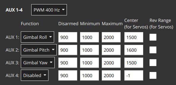
The PWM values to use for the disarmed, maximum, center and minimum values can be determined in the same way as other servo, using the Actuator Test sliders to confirm that each slider moves the appropriate axis, and changing the values so that the gimbal is in the appropriate position at the disarmed, low, center and high position in the slider. The values may also be provided in gimbal documentation.
Gimbal Control in Missions
Gimbal Manager commands may be used in missions if supported by the vehicle type. For example MAV_CMD_DO_GIMBAL_MANAGER_PITCHYAW is supported in multicopter mission mode.
In theory you can address commands to a particular gimbal, specifying its component id using the "Gimbal device id" parameter. However at time of writing (December 2024) this is not supported: all mission commands are sent to the (only) gimbal managed by the PX4 gimbal manager (if this is a MAVLink gimbal, it will be the gimbal with component id defined in the parameter MNT_MAV_COMPID, which is set by default to MAV_COMP_ID_GIMBAL (154)).
Gimbal movement is not immediate. To ensure that the gimbal has time to move into position before the mission progresses to the next item (if gimbal feedback is not provided or lost), you should set MIS_COMMAND_TOUT to be greater than the time taken for the gimbal to traverse its full range. After this timeout the mission will proceed to the next item.
Simulation / SITL
The following simulation environments come with a preconfigured simulated gimbal. You can test the gimbal using the QGroundControl UI or by sending driver commands
TIP
If you only need to test the gimbal driver, then you can do this on any model or simulators. Just make sure that the driver runs, using gimbal start in the MAVLink console, then configure the driver parameters.
Gazebo
To run the Gazebo simulation Quadrotor(x500) with gimbal (Front-facing) in Gazebo, use:
sh
make px4_sitl gz_x500_gimbal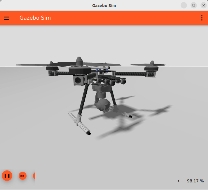
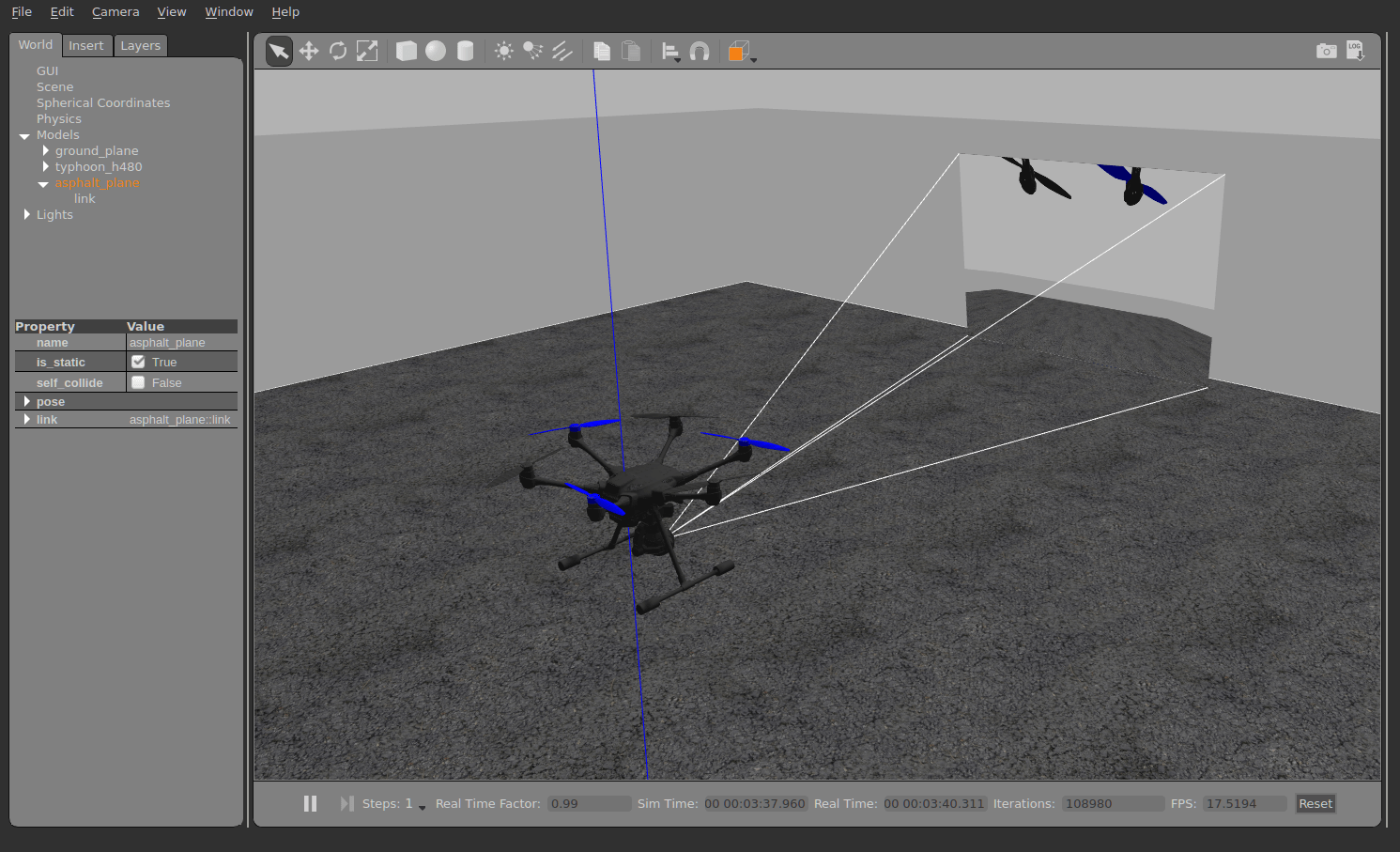
Gazebo Classic
To run the Gazebo Classic simulation Typhoon H480 model, use:
sh
make px4_sitl gazebo-classic_typhoon_h480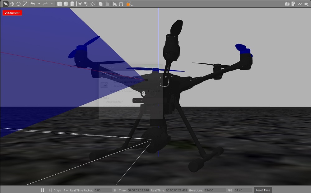
시험
QGC Testing
The on-screen gimbal control can be used to move/test a connected MAVLink camera:
Start your preferred simulator or connect to a real device.
Open QGroundControl and enable the on-screen camera control (Application settings).
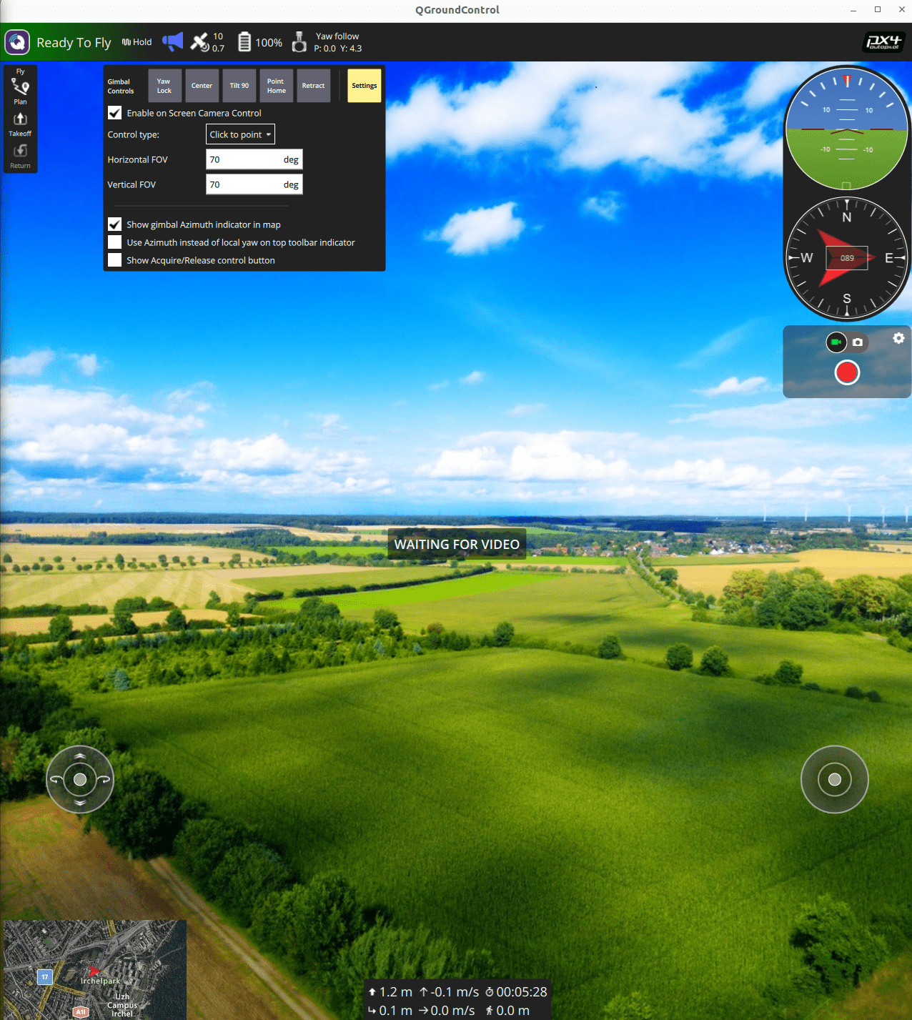
Make sure the vehicle is armed and flying, e.g. by entering with
commander takeoff.To change gimbal target position, click in the QGC GUI up, down, left, right, or use the buttons on the gimbal control (Center, Tilt 90, Yaw lock).
Driver Testing
You can test a gimbal by sending gimbal driver commands in the QGroundControl MAVLink Console:
- Start your preferred simulator or connect to a real device.
- Open QGroundControl and connect to your vehicle.
- Open the MAVLink Console using the menu: Analyze > Mavlink Console.
- Make sure the vehicle is armed and flying, e.g. by entering the command:
commander takeoff.
To check gimbal status enter:
sh
gimbal statusTo set the gimbal yaw to 30 degrees, use the command:
sh
gimbal test yaw 30More generally, you can set the angle or angular rate command using a command with this format:
sh
gimbal test <axis> <value>axis:<roll|pitch|yaw>for angles<rollrate|pitchrate|yawrate>for angular rates
value:<degrees>for angles<degrees / second>for angular rates
To set the MAVLink component that is in primary control of the gimbal:
sh
gimbal primary-control <sys_id> <comp_id>sys_id: MAVLink system IDcomp_id: MAVLink component ID
For other commands, see the gimbal driver module document.
MAVLink Testing
The gimbal can be tested by sending MAVLink gimbal manager commands using MAVSDK or some other MAVLink library.
Note that the simulated gimbal stabilizes itself, so if you send MAVLink commands, set the stabilize flags to false.