Connecting an RC Receiver to a PX4 Linux-based Autopilot
This topic shows how to setup a PX4 Linux-based autopilot to connect and use a supported RC receiver on any serial port.
S.Bus 이외의 RC 유형의 경우 수신기는 직렬 포트에 직접 연결하거나 USB-TTY 직렬 케이블(예: PL2302 USB-직렬 TTL 변환기)을 통하여 USB에 연결할 수 있습니다.
INFO
For an S.Bus receiver (or encoder - e.g. from Futaba, RadioLink, etc.) you will usually need to connect the receiver and device via a signal inverter circuit, but otherwise the setup is the same.
Then Start the PX4 RC Driver on the device, as shown below.
Starting the Driver
To start the RC driver on a particular UART (e.g. in this case /dev/ttyS2):
sh
rc_input start -d /dev/ttyS2For other driver usage information see: rc_input.
Signal Inverter Circuit (S.Bus only)
S.Bus is an inverted UART communication signal.
일부 직렬 포트/비행 컨트롤러는 반전된 UART 신호를 읽을 수 있지만, 대부분은 신호 반전을 복원하기 위하여 수신기와 직렬 포트 사이에 신호 인버터 회로가 필요합니다.
TIP
This circuit is also required to read S.Bus remote control signals through the serial port or USB-to-TTY serial converter.
이 섹션에서는 적절한 회로를 만드는 방법을 설명합니다.
필수 부품
- 1x NPN 트랜지스터 (예: NPN S9014 TO92)
- 1x 10K 저항
- 1x 1K 저항
INFO
Any type/model of transistor can be used because the current drain is very low.
회로 구성도/연결
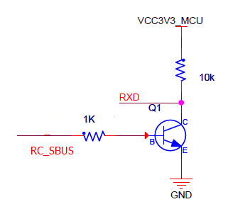
아래에 설명(그리고 회로 구성도)하는 바와 같이 회로 소자를 연결하십시오:
- S.Bus 신호선 → 1K 저항 → NPN 트랜지스터 베이스
- NPN 트랜지스터 방출 → GND
- 3.3VCC → 10K 저항 → NPN 트랜지스터 컬렉션 → USB-to-TTY rxd
- 5.0VCC → S.Bus VCC
- GND → S.Bus GND

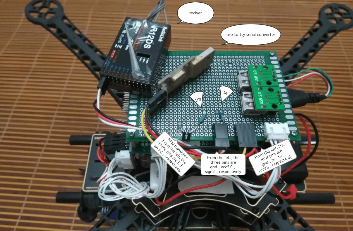
아래 이미지에서는 빵판에서 연결된 모습을 보여줍니다.
